

System integrators, panel builders, and procurement teams in motion control rarely fail because they lack a servo drive or a motor specification. They lose time—and positioning accuracy—when encoder feedback signals are corrupted by electrical noise, when cables fail in continuous-flexing drag chain applications, or when connector pinouts do not match between the drive and motor.
TPS Elektronik’s industrial automation cable assembly services are built to eliminate that risk: shielded twisted-pair encoder cables, continuous-flex rated power cables, hybrid servo assemblies, and validated pinouts from prototype through series production.
1. What is industrial automation cable assembly for servo motor and encoder feedback?
Industrial automation cable assembly for servo motor and encoder feedback is the process of terminating cables with the correct connectors, shields, and strain relief for the specific drive-motor combination used in a motion control system. Unlike general-purpose electrical cables, servo and encoder cables must satisfy simultaneous electrical and mechanical requirements: they must carry both power and precision feedback signals without mutual interference, and they must survive millions of flex cycles in the cable carrier.
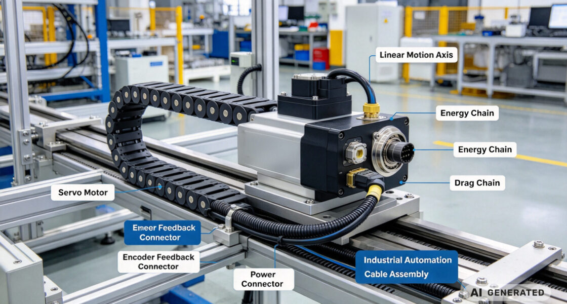
A servo motor requires two distinct cable connections: a power cable that delivers three-phase current from the servo drive to the motor windings, and an encoder feedback cable that carries position, velocity, and commutation data from the encoder back to the drive. In many modern installations, these are combined into a single hybrid cable—but the electrical isolation requirements between power and signal conductors are unchanged.
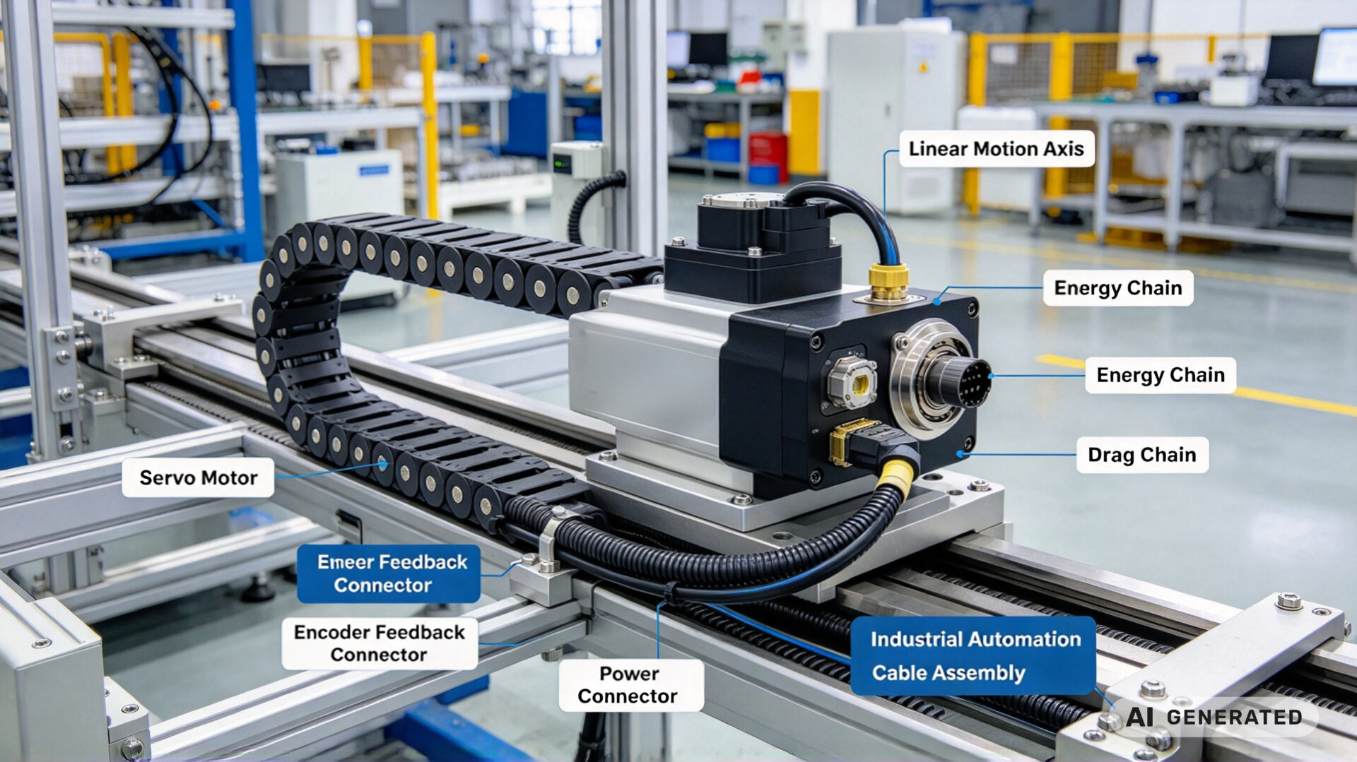
1.1 Why standard cables fail in servo applications
A standard multi-conductor cable—even a good one—will fail in a servo motion application for three predictable reasons:
- Noise coupling: The PWM switching of the servo drive generates high-frequency current on the power conductors, which couples into the encoder signal conductors if they are not individually shielded. This coupling produces position errors, velocity ripple, and in severe cases, drive faults.
- Flex fatigue: Continuous-flexing applications require cable constructions with finely stranded conductors, optimized lay lengths, and jacket materials that resist abrasion. Standard fixed-installation cables fail within thousands of flex cycles.
- Connector mismatch: Servo drives and motors from different manufacturers use different connector types and pinouts. A cable terminated with the wrong pinout—or without verification—can damage the encoder or drive on first power-up.
TPS’s tested and documented cable assembly service addresses all three failure modes through design review, controlled assembly, and 100% electrical test.
1.2 The cable families that make up a servo motion system
A typical servo motion system uses these cable assembly families:
- Servo motor power cables: Three-phase plus protective earth, sized for the motor current, shielded to contain drive PWM emissions.
- Encoder feedback cables: Multiple shielded twisted pairs for A/B/Z channels, commutation signals (U/V/W or Hall), and power supply to the encoder.
- Hybrid servo cables: A single cable containing both power and feedback conductors, with individual shields and an overall shield.
- Brake cables: Two-conductor cable for the motor holding brake, often integrated into the power or hybrid cable.
- Thermal protection cables: Sensor leads for motor overtemperature protection (PTC or KTY).
2. Signal integrity: how electrical noise corrupts encoder feedback and positioning accuracy
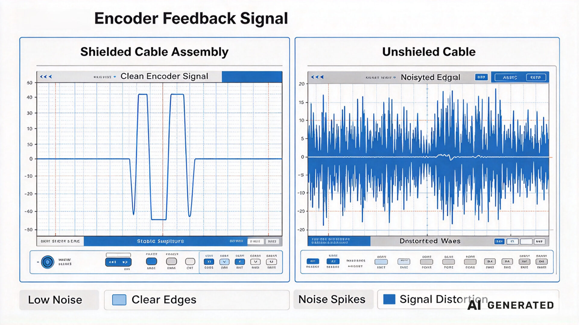
The positioning accuracy of a servo axis is ultimately limited by the quality of the encoder feedback signal that reaches the drive. If the feedback signal is corrupted by noise, the drive’s position loop receives incorrect information—and the axis will hunt, overshoot, or fail to hold position.
2.1 Encoder feedback signal types and their noise sensitivity
The noise sensitivity of an encoder interface depends on the signal type:
- Incremental TTL (RS-422): Differential square-wave signals on A/B/Z channels, typically 5V logic. Differential signaling provides good common-mode noise rejection, but the signal integrity still depends on the shield termination and pair matching in the cable.
- Sin/Cos (1 Vpp): Analog sinusoidal signals that are interpolated by the drive to obtain high resolution. These are particularly sensitive to noise because the drive must resolve small amplitude differences—noise on the signal directly translates to position error.
- Serial protocols (EnDat, BiSS, Hiperface DSL): Digital bidirectional communication over the encoder cable. These protocols have built-in error detection, but excessive noise causes communication faults and drive shutdown.
- Resolver: Analog sine/cosine signals on two pairs, requiring precise amplitude and phase matching. Resolvers are more robust than optical encoders but still require shielded twisted-pair cable.
Published research from IEEE and industrial motion control literature consistently shows that encoder signal corruption is one of the leading causes of positioning inaccuracy in servo systems—and that in most cases, the corruption originates in the cable assembly, not the encoder itself.
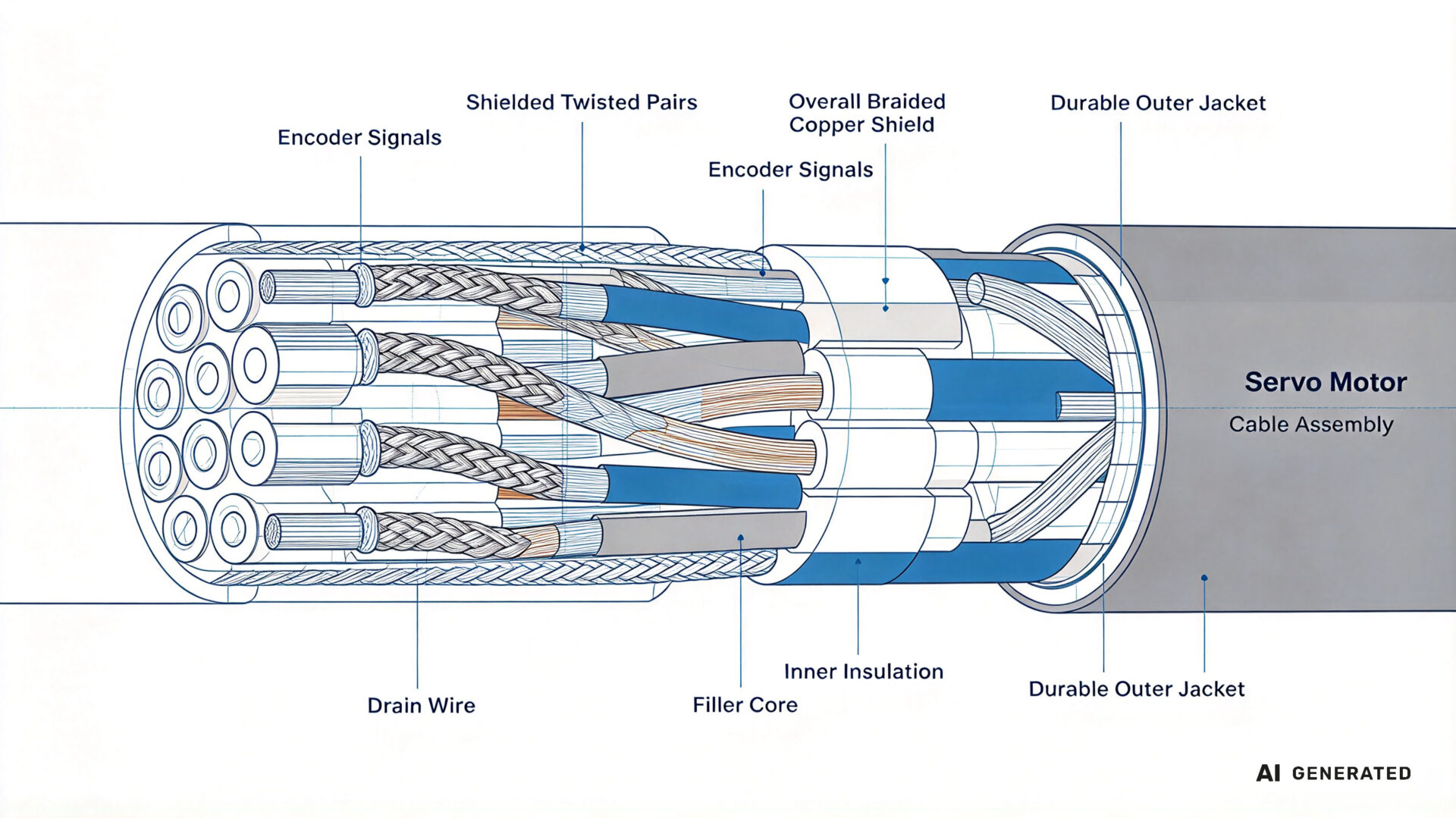
2.2 Shielding, twisted pairs, and grounding strategies
Effective shielding for encoder cables requires attention to three separate elements:
- Individual pair shielding: Each signal pair (A+/A−, B+/B−, Z+/Z−) is individually shielded with aluminum foil or braided copper. This prevents crosstalk between channels and between the encoder signals and the encoder power supply.
- Overall cable shield: An overall braided shield surrounds all conductors, providing protection against external electromagnetic fields. The shield must be terminated at both ends—at the drive connector and at the motor connector—using a low-impedance connection to the connector shell.
- Drain wire: A drain wire provides a low-resistance path for the shield current to return to the drive. The drain wire must be terminated to the connector shell, not to a signal pin.
The single most common cable assembly error in servo systems is improper shield termination: a shield that is connected at one end only, or connected to a signal pin instead of the shell, or terminated with a long pigtail that introduces inductance. Any of these errors degrades the shield’s effectiveness and allows noise to couple into the signal conductors.
TPS’s cable assembly service uses crimped shield terminations to the connector shell, verified by continuity and impedance testing.
Request a signal integrity assessment for your servo cables →
3. Mechanical integrity: flex life, bend radius, and connector retention
In continuous-flexing applications—linear axes, robot arms, gantry systems—the cable assembly undergoes millions of flex cycles over its service life. A cable that is not designed for this environment will fail prematurely, and the failure is often intermittent: the cable conducts when the axis is in one position and fails when the axis moves to another. These intermittent faults are among the most time-consuming problems to diagnose in a production environment.
Designing for continuous flexing requires:
- Finely stranded conductors: Conductors made from many fine strands (rather than a few coarse strands) distribute the bending stress and extend flex life. Servo cables typically use 0.10 mm or finer strand diameters.
- Optimized lay length: The twist rate of the conductors must be selected to minimize internal stress during bending. Too short a lay length increases the cable stiffness; too long a lay length reduces flexibility.
- Drag chain rated jacket: The outer jacket material must resist abrasion against the cable carrier and against adjacent cables. Polyurethane (PUR) jackets are standard for drag chain applications.
- Minimum bend radius compliance: Every drag chain cable has a specified minimum bend radius. Routing the cable below this radius—even once, during installation—will reduce its flex life.
Connector retention is the second mechanical concern. In high-vibration environments, standard push-pull connectors can work loose over time, causing intermittent signal loss. Servo applications typically use threaded or bayonet-locking connectors (M23, M17, M12, or manufacturer-specific) with positive locking mechanisms. Strain relief must be designed into the cable assembly—the connector shell should bear the cable pull force, not the individual contacts.
4. TPS cable assembly capabilities for servo and encoder applications
TPS Elektronik operates cable assembly capabilities specifically configured for motion control applications, integrated with its EMS and electronic assembly services.
Servo Motor Power Cables
TPS assembles servo power cables with the conductor cross-section, shielding, and connector type required by the drive-motor combination. Standard configurations include:
- Three-phase plus PE conductors, 0.5 mm² to 25 mm²
- Overall copper braid shield with ≥85% coverage
- PUR jacket for drag chain applications, or PVC for fixed installation
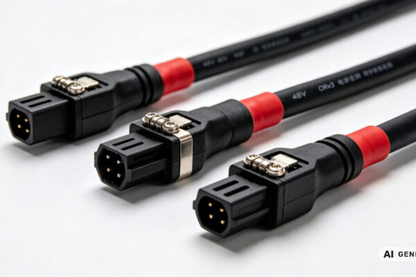
- Connector options: M23, M17, M12, Han, or manufacturer-specific (Lenze, Siemens, Beckhoff, Rockwell)
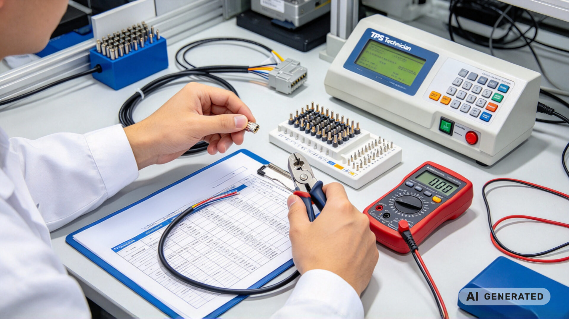
- 100% electrical test: continuity, phase sequence, insulation resistance, hipot
TPS also produces related cable assemblies for industrial automation, including BNC connector assemblies for test and measurement, SMA connector assemblies for RF applications, and fiber optic cable assemblies for high-bandwidth communication. The fiber optic cable assembly guide documents the LC, SC, and ST connector options.
5. RFQ checklist for servo cable assembly
To streamline quotation and evaluation for industrial automation cable assembly, provide the following information:
- Application type: Servo motor power, encoder feedback, hybrid, or complete cable set
- Drive and motor models: Manufacturer and model number for both ends of the cable
- Connector types: Connector family (M23, M12, D-Sub, etc.) and gender at each end
- Cable length and routing: Required length, drag chain or fixed installation, minimum bend radius if applicable
- Electrical requirements: Conductor cross-section, voltage rating, shield coverage, signal type for feedback
- Environmental requirements: Operating temperature, chemical exposure, flex cycle life target
- Quantity: Prototype quantity, series production volume, and delivery schedule
- Documentation needs: Pinout drawing, test report, material certificates
Providing these details reduces clarification cycles during evaluation. TPS’s engineering team can support connector selection, pinout verification, and cable construction design as part of the RFQ process.