For system integrators, panel builders, and procurement teams, cable assembly is rarely just wiring. It is often a critical interface where installation issues, delays, or rework can occur—particularly in customized or manually assembled systems.
TPS Elektronik provides EMS cable assembly services with a focus on consistent processes, including cutting, stripping, crimping or soldering, shielding, labeling, and final testing. The aim is to support installation workflows with clearly documented assemblies.
1. Why EMS cable assembly matters in RFQs
In procurement processes, delays are often linked to uncertainty rather than pricing. Common issues include unclear pinouts, inconsistent labeling, or missing test documentation.
An EMS-based approach treats each cable assembly as a controlled product. This typically includes defined process steps, documented testing, and traceability. For system integrators, this can support alignment with broader electronics manufacturing processes rather than managing cable assembly as a separate task.
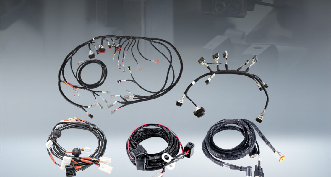
2. Scope of cable assembly: from power to fiber
Cable assembly requirements often include a mix of power, signal, RF, and fiber applications. Each type has different performance criteria and testing requirements.
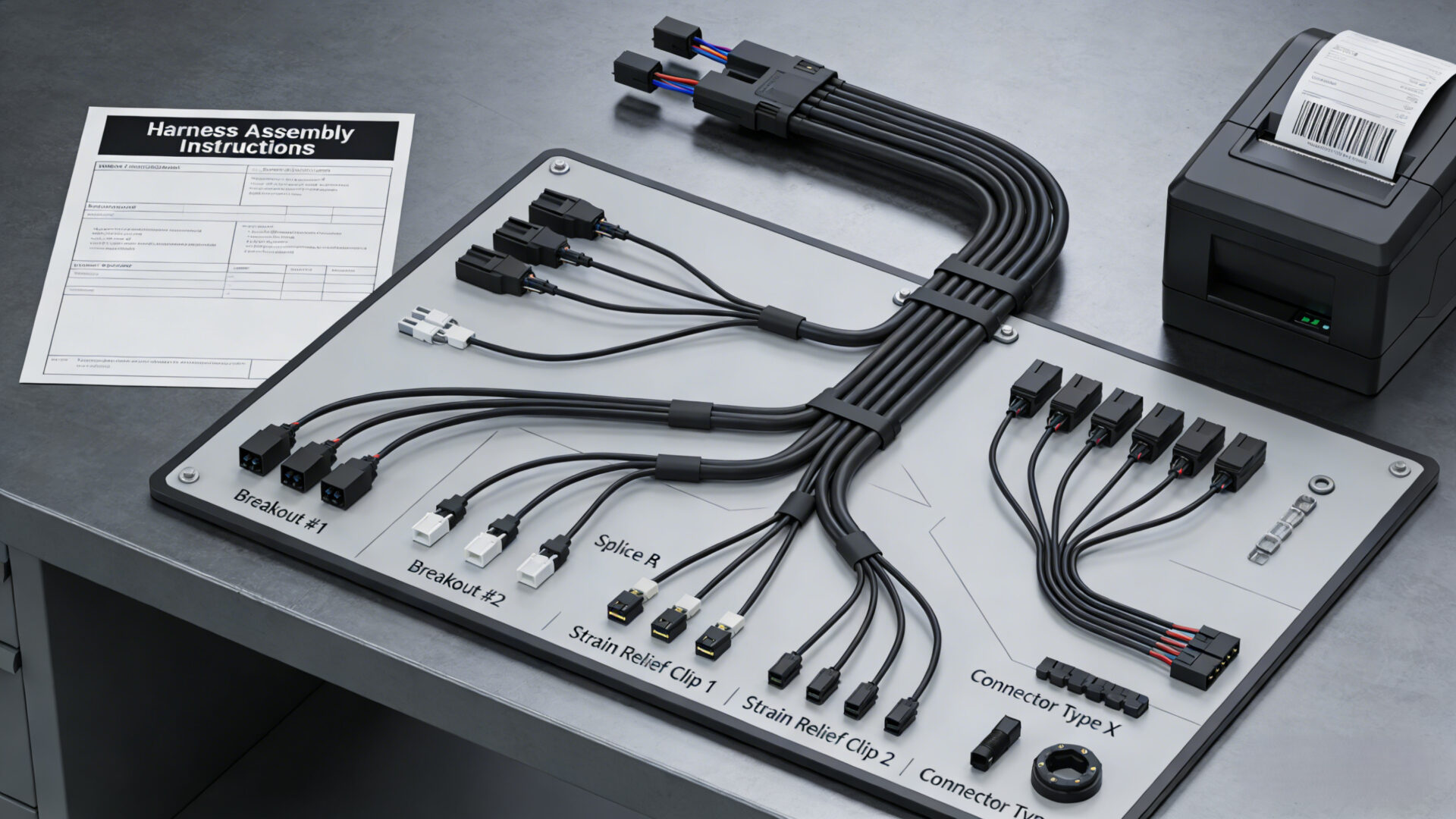
2.1 Wire Harnesses and Panel Wiring Sets
In panel building, wire harnesses function as pre-defined installation sets rather than individual cables. They typically include:
- Defined lengths and routing logic
- Labeled ends for installation clarity
- Standardized terminals or ferrules
Structured harness design can support consistent installation and reduce wiring variability.
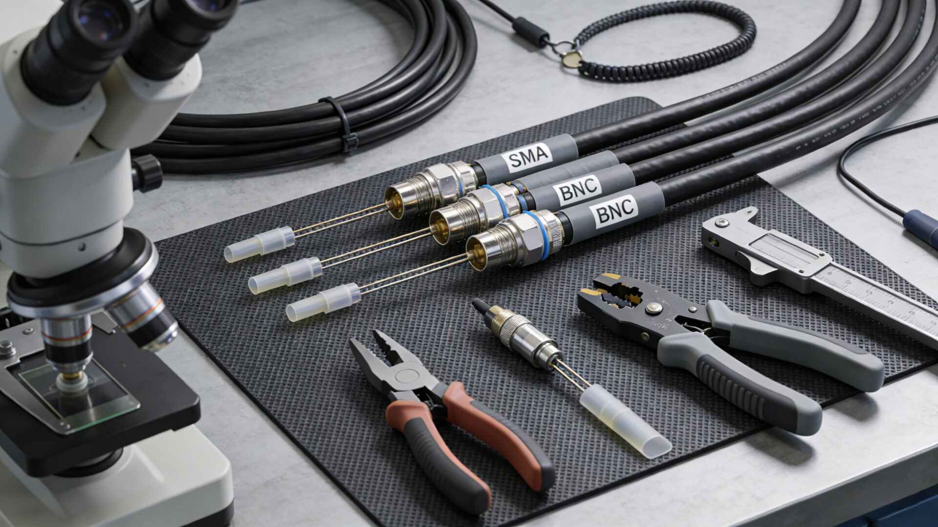
2.2 RF/Coax Cable Assemblies (SMA, BNC, TNC)
RF cable assemblies require careful handling, as small deviations in stripping, shielding, or connector termination may affect signal performance.
Typical considerations include:
- Connector type selection (e.g., SMA, BNC, TNC)
- Shielding integrity
- Mechanical handling and torque
Specifications should be defined clearly in the RFQ, especially where RF performance is relevant.
2.3 Fiber Optic Cable Assemblies (LC, SC, ST)
Fiber optic assemblies differ significantly from electrical cables. Performance depends on:
- Termination quality
- Cleanliness of connectors
- Bend radius management
- Documented test results
Acceptance criteria such as insertion loss or return loss should be defined where applicable.
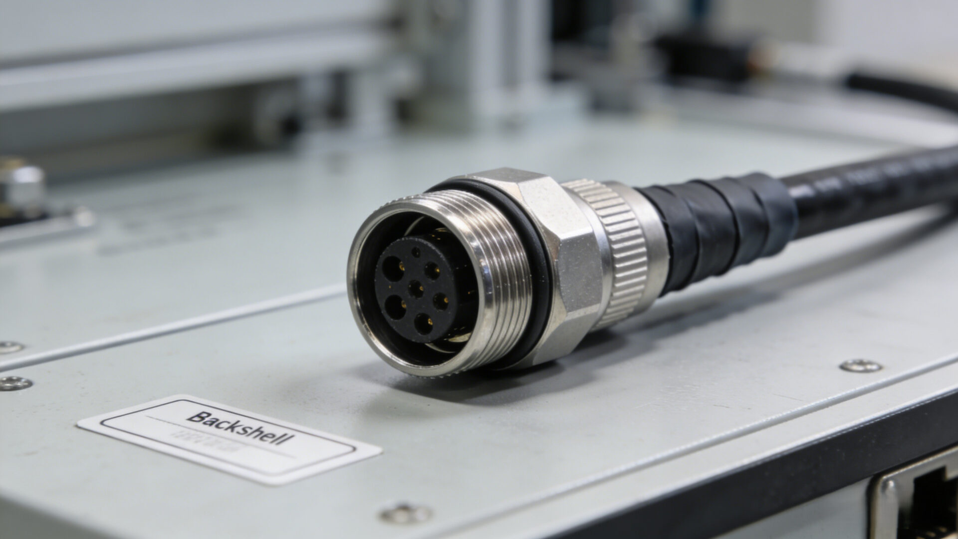
2.4 Circular Connectors (M8, M12 and Others)
Circular connectors are widely used in industrial environments due to their mechanical robustness and guided mating.
Typical advantages include:
- Reduced risk of incorrect connections
- Simplified installation and maintenance
- Compatibility with field service requirements
They are commonly used in sensor systems, industrial I/O, and harsh environments.
3) Connector Selection Considerations
Connector selection has a direct impact on system reliability and installation effort. Incorrect selection may lead to mechanical stress, ingress issues, or signal degradation.
3.1 Waterproof Connectors and IP Considerations
The term “waterproof” is often used imprecisely. In engineering terms, this relates to ingress protection (IP rating) and application conditions.
RFQs should specify:
- Environmental exposure (e.g., washdown, outdoor use, oils, UV)
- Sealing requirements
- Cable and connector compatibility
Reference to IEC IP standards can provide a structured framework.
3.2 Circular Connectors in Industrial Environments
Circular connectors support installation efficiency through:
- Keyed mating systems
- Mechanical stability
- Ease of replacement in field conditions
They are often used where serviceability and robustness are required.
3.3 Data vs Power Connectors
Data and power cable assemblies have different requirements:
- Data cables: impedance control, shielding continuity, routing constraints
- Power cables: current capacity, temperature rise, mechanical strain
Combining these requirements without distinction may lead to performance issues.
3.4 Military-Style Connectors and Requirements
Terms such as “military spec connectors” typically indicate higher requirements for:
- Environmental resistance
- Documentation and traceability
- Defined materials and finishes
RFQs should clearly define applicable standards and any export-control considerations.
3.5 Pin-Count Specification in RFQs
Specifying only the number of pins (e.g., “3-pin connector”) is not sufficient.
RFQs should include:
- Manufacturer and series
- Part number
- Keying and contact type
- Wire specifications
- Mating connector
This helps reduce ambiguity and follow-up clarification.
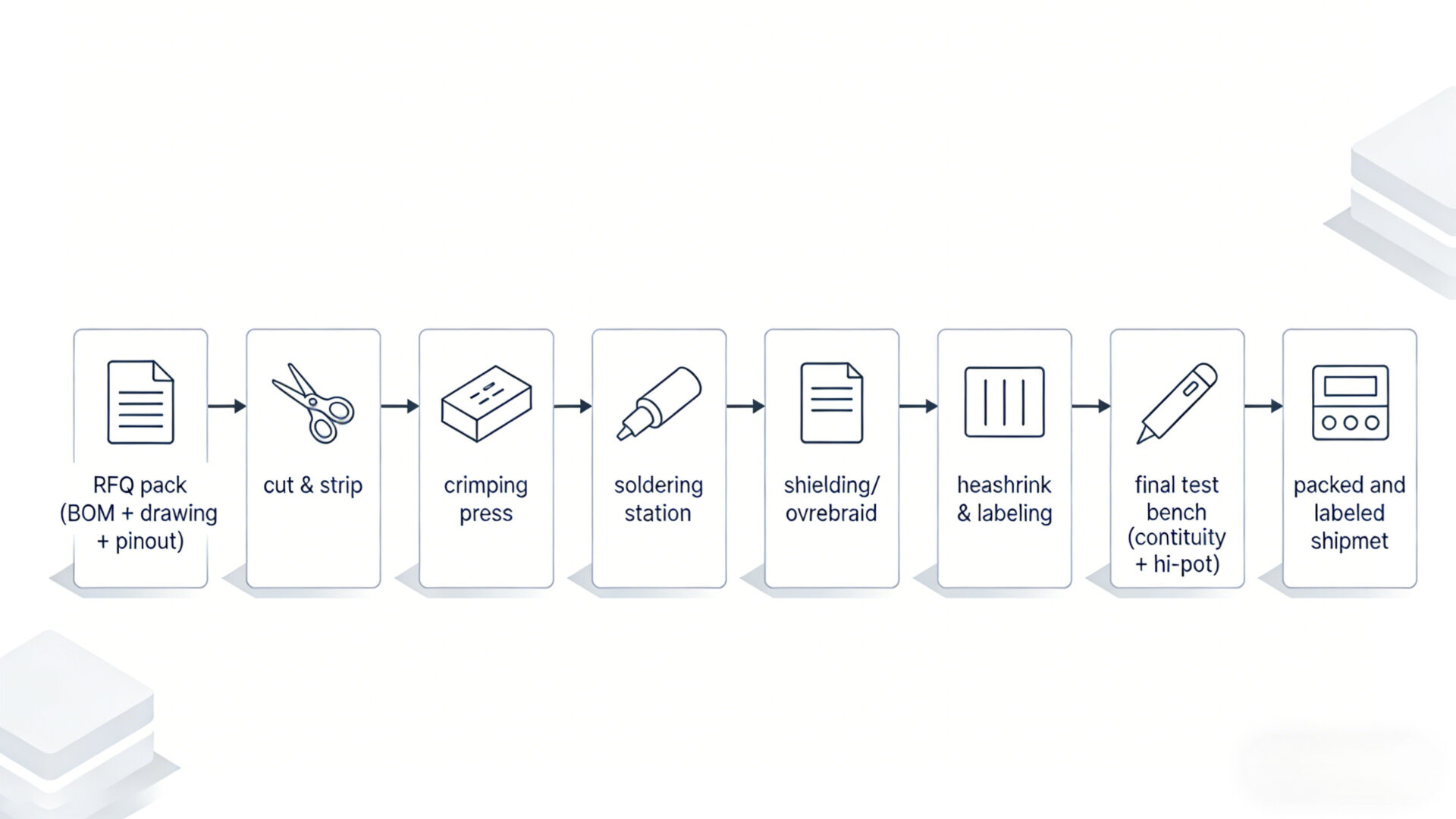
4) Process Control in Cable Assembly
Cable assembly involves multiple process steps, including:
- Cutting and stripping
- Conductor preparation
- Crimping or soldering
- Shielding and strain relief
- Labeling and finishing
- Final inspection and testing
Standardization of these steps can support consistent results, especially for repeated builds or product variants.
5) Testing and Documentation
Cable assemblies may fail immediately (e.g., incorrect wiring) or over time (e.g., mechanical stress or corrosion).
Typical testing approaches include:
- Continuity testing
- High-voltage (hi-pot) testing where required
- RF measurements (e.g., VNA) for coaxial cables
- Optical testing (e.g., OTDR) for fiber
Documentation may include:
- Test records
- Traceability information
- Labeling specifications
- Nonconformance procedures
Standards such as IPC/WHMA-A-620 are commonly referenced for workmanship expectations.
6) RFQ Checklist for Cable Assemblies
A structured RFQ can reduce clarification cycles and improve quote accuracy.
Typical RFQ content:
- BOM and drawings: connectors, accessories, components
- Pinout: wiring definitions and shielding rules
- Length and tolerances: overall and branch lengths
- Wire specifications: gauge, insulation, temperature rating
- Environment: operating conditions and protection requirements
- Test requirements: continuity, hi-pot, RF/fiber testing if needed
- Labeling: format, language, positioning
- Packaging: handling and protection requirements
- Volumes: prototype and production quantities
FAQ
What should be specified for cable connectors in an RFQ?
Manufacturer, series, part number, contact type, wire range, and mating connector.
How should waterproof requirements be defined?
By describing environmental conditions and sealing expectations, rather than using general terms.
When are circular connectors appropriate?
In applications where installation reliability and serviceability are important.
How do RF and fiber testing differ from basic continuity testing?
They may require additional measurement methods such as VNA or OTDR, depending on performance requirements.
What do military-style connectors typically imply?
Higher requirements for environmental resistance, documentation, and traceability, depending on the application.


