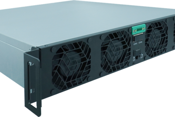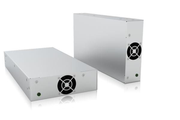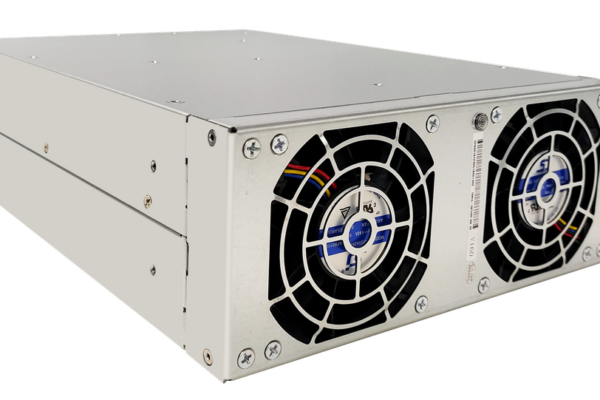


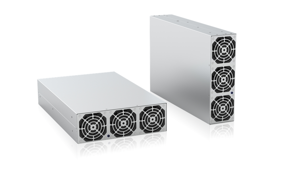
For battery test, cell formation, and energy-recovery equipment, the power stage must do more than meet a nominal voltage and wattage. It must move energy reliably in both directions, interact cleanly with the three-phase grid, respond predictably under automation, and fit the thermal and mechanical limits of the cabinet. The TPS-BM9014KTIF 90 V bidirectional power module addresses that system-level requirement with 14 kW AC-to-DC operation, 13 kW DC-to-AC regenerative operation, CAN communication, and parallel expansion for higher-power platforms.
- Decision summary for technical buyers
- How the bidirectional architecture supports test systems
- Key specifications and what they mean
- Application fit and selection logic
- Electrical, thermal, mechanical, and control integration
- Compliance, reliability, and qualification
- RFQ checklist and TPS project support
- FAQ
TPS-BM9014KTIF: decision summary for technical buyers
The TPS-BM9014KTIF is a three-phase, isolated, bidirectional AC/DC power module for controlled energy transfer between a 380/400/415 VAC grid and a nominal 90 VDC bus. In source mode, it supplies up to 14 kW and 155.6 A on the DC side. In regenerative mode, it accepts up to 13 kW and 144.5 A from the DC side and returns energy to the AC network. This combination is especially relevant when a test sequence repeatedly charges and discharges batteries or other energy-storage devices: instead of dissipating discharge energy entirely as heat, the system can recover it through a controlled DC-to-AC path.
For system integrators and panel builders, the module provides a compact building block measuring 268 × 86 × 435 mm and weighing no more than 10 kg. Forced-air cooling uses a front-inlet/rear-outlet airflow path, while CAN supports supervisory control. Up to eight modules can be expanded in a system, subject to validation of current sharing, grid connection, protection coordination, cabinet airflow, and the application control strategy. Procurement teams should therefore compare not only the unit price, but also conversion losses, cooling demand, cabinet volume, integration effort, compliance evidence, and supplier support.
The right buying question is not simply “Is 14 kW enough?” It is: “Does the operating envelope, control interface, recovery path, protection concept, and environmental derating match our complete machine?” TPS Elektronik GmbH can support this evaluation with product selection, equivalent solution assessment, integration consultation, and project-level coordination for global B2B customers. Start with the TPS bidirectional power-module portfolio, then confirm the operating points in an RFQ.
Source operation powers the DC bus; regenerative operation routes available DC energy back toward the grid.
How the bidirectional architecture supports test systems
Conventional test benches often combine a DC source with a separate electronic load. That arrangement can be appropriate for low-duty or low-energy tests, but it usually converts discharge energy into heat. A bidirectional module combines controlled sourcing and regenerative sinking in one power stage. During charging, AC energy is converted to regulated DC. During discharge, the power direction reverses and eligible energy is converted back to AC. This reduces the thermal burden associated with purely dissipative loading and can improve the energy economics of high-cycle production or endurance testing.
The TPS-BM9014KTIF uses three-phase operation without a neutral conductor (3Ph+PE) and bidirectional high-frequency isolation. Its specified power factor is 0.99 at 380 VAC and full load when grid THDu is no more than 2%. Input/output current THDi is specified below 5% under the same reference conditions. These figures matter because grid interaction affects upstream cable sizing, protective devices, transformer loading, and the electromagnetic environment of the complete machine. They should be verified at the actual operating points and with the intended grid impedance.
Seamless bidirectional switching is intended to support fast-changing automated test sequences. Nevertheless, the response of a complete test channel also depends on DC-bus capacitance, battery impedance, contactors, pre-charge, measurement latency, CAN command timing, and application software. If the project requires programmable waveform generation, laboratory-grade sequences, or a self-contained instrument UI, compare the module architecture with a regenerative programmable DC power platform. The correct choice depends on whether the engineering team needs an embedded module or a ready-to-operate instrument.
Key specifications and what they mean for selection
| Parameter | Specified value | Engineering relevance |
|---|---|---|
| AC-to-DC rating | 14,000 W; 90 VDC; 155.6 A | Defines maximum source-side test power and current. |
| DC-to-AC rating | 13,000 W; 90 VDC; 144.5 A | Defines regenerative discharge capability; it is not identical to source rating. |
| AC interface | 3Ph+PE; 380/400/415 VAC; 323-456 VAC; 50/60 ±5 Hz | Check site grid, branch protection, disconnect, and wiring. |
| Power quality | PF 0.99; THDi <5% at stated conditions | Supports efficient grid use; validate at system level. |
| DC regulation | ±1% voltage accuracy; 1.5 V ripple | Compare with DUT tolerance and measurement objectives. |
| Peak efficiency | 92% AC→DC; 91.5% DC→AC | Basis for cooling and operating-cost estimates, not a full efficiency map. |
| Environment | -10 to 45°C full load; 45 to 60°C derated to 80%; 5-95% RH non-condensing | Sets cabinet cooling and ambient limits. |
| Control and expansion | CAN; up to 8 modules; current-sharing imbalance <5% | Requires protocol, master-control, and parallel-layout confirmation. |
The 90 VDC rating must be treated as an operating design point, not as permission to apply any low-voltage battery directly. Confirm the required minimum and maximum DUT voltage, current polarity, transient behavior, cable drop, and connector temperature rise. The specification also warns that DC-side voltage above 150 VDC can cause power failure. A suitable system should therefore include voltage supervision and a protection concept that prevents abnormal battery or bus conditions from exceeding the module boundary.
A valid selection must satisfy all four envelopes simultaneously—not just nominal power.
Application fit and selection logic
Battery module and pack-subassembly testing
The module is a strong candidate when the DUT operates around a 90 V bus and the test plan requires repeated charge/discharge cycles. Engineers should translate the profile into four values: maximum source power, maximum regenerative power, peak current, and duration at each operating point. Because the two directions have different ratings, a test with 14 kW charge and 14 kW continuous regeneration does not fit a single module. Either the regenerative requirement must be limited, or the architecture must be resized.
Series cell formation and energy-recovery aging
In formation or aging equipment, energy recovery can reduce heat that otherwise must be removed from load banks. Channel architecture is crucial: decide whether each module serves one 90 V string, several controlled channels through downstream conversion, or a common DC bus. For lower-voltage cell-side systems, review the related 14 V cell-formation power-module approach or a 15 V bidirectional solution; these illustrate why voltage class and channel topology must be established before selecting wattage.
Use-case fit starts with the voltage window and two-direction load profile, then moves to controls, safety, and qualification.
Bidirectional power validation and production equipment
For inverter, storage, or DC-bus component validation, confirm whether the module’s ±1% voltage accuracy and 1.5 V ripple support the acceptance criteria. Precision measurement may still require external calibrated instruments and synchronized data acquisition. TPS can help separate the power-delivery function from the measurement function, so the RFQ defines both the converter and any additional instrumentation instead of assuming one device covers every requirement.
If the required DC voltage is hundreds of volts rather than 90 V, compare other voltage classes such as the 750 V bidirectional module platform. This prevents a common sourcing error: selecting by kW while overlooking the current and voltage architecture.
Electrical, thermal, mechanical, and control integration
Electrical design and protection coordination
The AC connection is 3Ph+PE without neutral, with a stated input-current limit of 28 A in AC-to-DC operation. Cable sizing and protective devices must follow the actual installation method, ambient temperature, local regulations, inrush behavior, fault level, and the final machine’s conformity assessment. On the DC side, busbars or short low-resistance conductors are usually preferable at currents above 140 A. The integrator should calculate voltage drop, terminal heating, short-circuit energy, polarity protection, pre-charge, contactor rating, discharge paths, and safe isolation for service.
Airflow, derating, mounting, and service access
Forced-air cooling is only effective when the cabinet preserves the front-inlet/rear-outlet path and prevents hot-air recirculation. Peak efficiency implies that meaningful waste heat remains at rated power, so cabinet design should use a conservative thermal calculation rather than subtracting a single peak-efficiency number at all loads. The module supports full-load operation from -10°C to 45°C; between 45°C and 60°C, power is derated to 80%. Above 1,000 m altitude, the specified derating is 1% per additional 100 m up to 3,000 m.
The 268 × 86 × 435 mm envelope can support dense integration, but surrounding clearance, fan replacement, terminal access, bend radius, and removable-unit strategy still need definition. TPS also supports cabinet and chassis work; a 6U 19-inch power-integration concept is useful when the project requires an engineered subrack rather than loose modules.
CAN control and parallel expansion
CAN communication should be treated as an integration work package. Request the protocol definition, state machine, command and feedback objects, update rates, fault codes, watchdog behavior, addressing method, and termination requirements. For parallel systems, also define master coordination, start-up sequencing, interlocks, emergency stop behavior, current-sharing validation, and failure handling. The specification lists expansion to eight modules and current-sharing imbalance below 5%; the exact deliverable configuration should be confirmed with TPS before freezing the system architecture.
The module is one layer of the machine; successful deployment depends on the surrounding protection, controls, cooling, and safety architecture.
Compliance, reliability, and qualification
The specification states that the design is intended to comply with IEC 62477-1 and EN 55032. IEC 62477-1 addresses safety requirements for power electronic converter systems and equipment, while EN 55032 addresses multimedia-equipment emissions. These references are useful inputs, but they do not replace a project-specific compliance review. The final machine may require additional safety, EMC immunity, grid-connection, functional-safety, environmental, or industry standards depending on its market and application.
Similarly, wording that a product “can pass” UL, CE, or TÜV assessment should not be interpreted as proof that a specific certificate or mark already covers every delivered configuration. Procurement should request the exact declaration, certificate, test report, report number, model coverage, revision, and issuing body required for the project. TPS can coordinate the available documentation and identify gaps early, before qualification samples or production commitments.
Reliability evaluation should include the stated protection functions, overtemperature shutdown behavior, fan life, fault logging, recovery after grid disturbance, and the consequence of a single-module failure in a parallel bank. The operating environment is specified as 5-95% relative humidity without condensation and storage from -40°C to 70°C. If the equipment will encounter conductive dust, salt mist, vibration, shock, or condensation, state those conditions in the RFQ because they are not resolved by a broad temperature rating alone.
RFQ checklist and TPS project support
A technically complete RFQ shortens selection time and reduces commercial risk. Send TPS the information below even if some values are preliminary:
- DUT type, nominal voltage, minimum/maximum voltage, source current, regenerative current, and transient limits.
- Continuous and peak power in both directions, duty cycle, cycle time, and annual operating hours.
- Grid voltage/frequency, country of installation, transformer or facility limits, and regeneration permission.
- Number of channels, required module redundancy, future expansion, and expected current-sharing performance.
- CAN/PLC/test-software architecture, control-loop requirements, data logging, and fault-response expectations.
- Cabinet dimensions, airflow constraints, ambient temperature, altitude, humidity, acoustic targets, and service access.
- Required certificates, standards, validation documents, sample schedule, forecast volume, and delivery milestones.
With these inputs, TPS can help confirm whether the 14 kW TPS-BM9014KTIF configuration fits the operating envelope, whether parallelization is appropriate, or whether another TPS module or customized system is the better commercial and technical choice. This is particularly valuable for system integrators and panel builders who need one supplier conversation to cover the power module, mechanical integration, cooling, wiring interfaces, and project documentation.
TPS supports the transition from specification review to a project-ready bidirectional power solution.
Confirm your 90 V regenerative power architecture
Review the TPS-BM9014KTIF product page, then send your voltage window, two-direction power profile, grid data, cabinet constraints, compliance needs, and schedule. TPS Elektronik GmbH can support product selection, equivalent solutions, customization, integration, and engineering consultation for international B2B projects.
Frequently asked questions
Is the TPS-BM9014KTIF rated at 14 kW in both directions?
No. The specified AC-to-DC output capacity is 14 kW, while the specified DC-to-AC input capacity is 13 kW. Size the system against the larger requirement in each direction and the actual duty cycle.
Can multiple modules be connected for higher power?
The specification lists expansion to eight modules and current-sharing imbalance below 5%. The final parallel architecture, protection, CAN coordination, busbar layout, derating, and failure behavior should be confirmed with TPS for the project.
What grid connection does the module require?
It is specified for 3Ph+PE without neutral, nominally 380/400/415 VAC, with a 323-456 VAC operating range and 50/60 ±5 Hz adaptive control. Site-specific regeneration rules and protection requirements remain part of the machine design.
Is the product already certified for every market?
The specification states design intent for IEC 62477-1 and EN 55032 and notes the ability to pass UL, CE, and TÜV assessment. Request the exact current certificates and model coverage needed for your destination market; do not infer final-machine compliance from a component statement.
What should I send for a fast quotation?
Provide the DC voltage range, source and regenerative current/power, duty cycle, AC grid, channel count, ambient and altitude, control requirements, certification target, quantity, and delivery schedule. Use the TPS solution inquiry page to start the technical review.