

Programmable DC Power | Supplier Evaluation & RFQ Guide
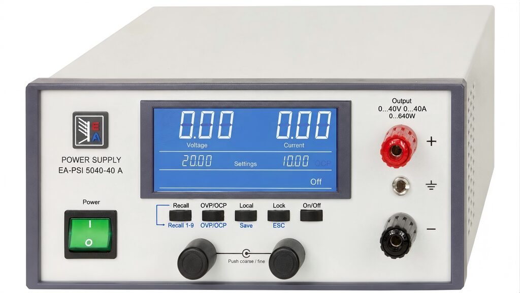
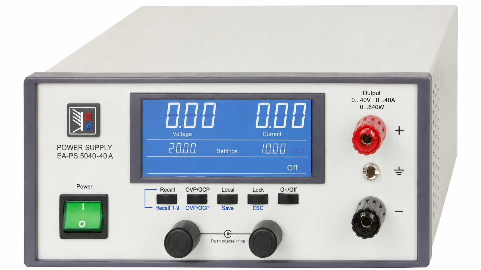
The EA-PS 5040-40A combines a 0–40 V, 0–40 A auto-ranging output with up to 640 W in a compact desktop format. This guide helps electrical engineers, system integrators, panel builders, and procurement teams decide whether it fits their test station—and what to confirm before ordering.
1. Decision Summary: Where the EA-PS 5040-40A Fits
For teams evaluating a programmable desktop DC power supply, nameplate ratings are only the start. The practical question is whether one source can cover the voltage-current combinations, operating workflow, protection behavior, automation interface, and documentation expected by the project. The EA-PS 5040-40A is a strong candidate when the device under test operates below 40 VDC, may require current up to 40 A, and never needs more than 640 W at one operating point.
Its auto-ranging power stage is commercially important. A conventional fixed-range supply can force a buyer to oversize the unit or purchase several instruments. This model can provide higher current at lower voltage or higher voltage at lower current, subject to the 640 W ceiling and the 40 V/40 A limits. At 16 V, for example, 40 A corresponds to 640 W; at 40 V, the full power limit corresponds to 16 A. The unit cannot deliver 40 V and 40 A simultaneously because that would require 1.6 kW. Engineers should therefore compare the complete load profile—not only maximum voltage and maximum current—with the allowable power envelope.
The instrument is particularly relevant to engineering benches, service stations, quality-control fixtures, component characterization, low-voltage electronics, automotive subassemblies, actuators, controllers, and small automated test systems. Front output terminals support quick bench work, while an additional rear screw-terminal output is useful for a more permanent fixture. USB connectivity, supplied control resources, and stored presets can reduce repetitive setup work.
For a purchasing decision, use the EA-PS 5040-40A product page to identify the exact article, then ask TPS to validate the duty cycle, cabling, accessories, software environment, current availability, and delivery scope. If the application needs a different voltage, power class, interface, cabinet format, or source/load architecture, TPS can propose an equivalent programmable power solution rather than forcing the project into one model.
2. Key Specifications to Put on the Evaluation Sheet
| Parameter | EA-PS 5040-40A | Why it matters in an RFQ |
|---|---|---|
| DC output | 0–40 V, 0–40 A, 0–640 W | Defines the operating envelope; voltage, current, and power limits apply together. |
| AC input | 90–264 VAC, 45–65 Hz, active PFC, power factor >0.99 | Supports global deployment; plug, cord, fuse, and site requirements still need confirmation. |
| Voltage performance | Load regulation <0.08%; line regulation <0.02%; accuracy ≤0.2% | Helps assess stability and measurement margin for the DUT. |
| Voltage ripple | <80 mVpp; <10 mVrms | Must be checked against noise-sensitive loads and the stated measurement bandwidth. |
| Current performance | Load regulation <0.15%; line regulation <0.02%; accuracy ≤0.2%; ripple <160 mApp | Relevant to current-driven loads, characterization, and repeatability. |
| Dynamic regulation | <1 ms for 10–100% load change | A first indicator for changing loads; request application validation for demanding transients. |
| Protection | OVP, OCP, OPP, OTP | Protects the DUT and supply; confirm threshold strategy and shutdown/restart behavior. |
| Controls and interface | Blue LCD, rotary controls, key lock, 9 presets, USB | Supports manual use and basic automation; verify OS, driver, and command compatibility. |
| Mechanical / environment | 200 × 87 × 331 mm enclosure; 4.3 kg; fan cooling; 0–50 °C operation | Drives bench space, airflow, acoustic, transport, and fixture decisions. |
Values are based on the supplied product specification. The stated dimensions refer to the enclosure rather than every protruding part. Final procurement should use the current datasheet and quotation.
3. Selection Logic for Engineers and Procurement
3.1 Map the Complete Power Envelope
Create a table of nominal, startup, peak, fault, and endurance-test points. Confirm that every combination stays below 40 V, below 40 A, and at or below 640 W. Include cable losses and required voltage at the DUT terminals. If the load draws pulses, has high input capacitance, or changes rapidly, provide a waveform or current-versus-time profile with the RFQ. This lets TPS evaluate dynamic behavior rather than relying on a static wattage calculation.
3.2 Decide Between Manual Operation and Automation
The LCD, rotary controls, lock function, and nine memories make the unit practical for repeated manual procedures. USB enables remote operation, and the source material lists Windows control software and LabVIEW VIs. For a new automated test equipment project, however, specify the PC operating system, required programming environment, command protocol, trigger expectations, data logging, electrical isolation needs, and planned support life. Do not assume that a physical USB port alone guarantees compatibility with a current software image or validated production sequence.
3.3 Translate DUT Risk into Protection Settings
OVP, OCP, OPP, and overtemperature shutdown are valuable only when their thresholds reflect the DUT’s safe operating area. Include acceptable trip values, permissible overshoot, restart policy, and whether an operator or control program must acknowledge a fault. For sensitive prototypes, begin with conservative limits and validate the shutdown behavior using a non-critical load.
4. Application Fit—and When to Choose Another Architecture
Typical fits include powering 12 V, 24 V, and 36 V subsystems; testing controllers, motors, actuators, lighting modules, converters, and electronic assemblies; burn-in at controlled DC conditions; repair and service diagnostics; and repeatable production checks. The 40 A ceiling is useful for low-voltage equipment with substantial current demand, while auto-ranging improves utilization across mixed DUT families.
This desktop source is not automatically the best choice for every power project. A fixed cabinet supply may be more appropriate for continuous machine operation; a higher-voltage programmable source is required above 40 V; a bidirectional source/load is needed when energy must flow back from the DUT; and a regenerative load is more efficient for sustained energy absorption. TPS can help compare these architectures. For a lower-power desktop reference, review the EA-PS 3200-02 C desktop power supply. For broader intelligent desktop capability, see the EA-PSI 9000 DT overview. Higher-power rack projects can be evaluated against the EA-PS 10000 3U platform, while energy-absorbing systems may require a regenerative DC load.
The selection principle is simple: choose the architecture from the load profile and test objective, not from a familiar model number. TPS has product and solution capability across desktop instruments, programmable power, bidirectional modules, loads, mechanical integration, and project-level engineering. That makes it possible to quote the requested unit or propose an equivalent solution when the original requirement is incomplete or constrained.
5. Integration and Installation Considerations
The enclosure is listed as 200 × 87 × 331 mm and 4.3 kg. Procurement should allow additional space for feet, terminals, connectors, cable bend radius, and ventilation. Fan-cooled equipment should not be boxed into an unventilated shelf. If several instruments operate together, assess aggregate heat, noise, mains current, and access for maintenance.
At 40 A, output wiring becomes a system component. Specify conductor cross-section, length, insulation, temperature rating, termination method, touch protection, and acceptable voltage drop. The documentation shows front outputs and an additional rear screw-terminal output, including sense connections on the rear illustration. Ask TPS which terminal set, safety adapter, cable assembly, and remote-sense practice apply to the quoted configuration. The listed optional safety adapter is rated to a maximum of 32 A, so it should not be assumed suitable for every 40 A use case.
Panel builders should also define protective devices and interfaces outside the instrument: upstream disconnect, mains protection, emergency-stop behavior, interlocks, fixture contactors, and safe discharge of connected capacitance. System integrators should capture the instrument identity and configuration in the test software, prevent unauthorized front-panel changes, and create a recovery procedure for communication loss or a protection trip.
6. Compliance, Documentation, and Reliability Review
The supplied legacy specification states that 40 V models were designed according to SELV requirements referenced to EN 60950 and that EMC performance was stated according to EN 55022 Class B. These references are useful historical design information, but they should not be treated as a current project declaration or as proof of compliance with every market requirement. Standards and regulatory frameworks evolve, and the applicable evidence depends on the destination, installation, end product, and date of supply.
For an RFQ, request the current datasheet, applicable declaration of conformity, available safety or EMC reports, UKCA/CE status where relevant, serial-number or revision traceability, warranty terms, calibration statement or certificate options, and end-of-life information. If the supply will be built into a production fixture or exported with a machine, identify the final compliance responsibility and required technical-file documents before purchase.
Reliability evaluation should include operating temperature, cooling path, expected daily duty cycle, load profile, switching frequency, environmental contamination, preventive maintenance, and spare strategy. The specification lists operation from 0 to 50 °C and storage from -20 to 70 °C. Ask whether derating, fan service, or calibration intervals apply to the actual deployment.
7. What TPS Adds Beyond Supplying the Instrument
A BoFu buyer often needs more than a part number. TPS Elektronik GmbH can review the operating points, check whether the auto-ranging envelope is appropriate, identify an equivalent programmable source when requirements change, and coordinate accessories or system-level integration. This is valuable for global B2B customers who need technical and commercial alignment across engineering, procurement, and project delivery.
For a direct product inquiry, reference article HEA3591 and manufacturer code 05100306 on the EA-PS 5040-40A shop listing. For a broader request—including alternatives, higher power, integration, or a complete test-power concept—contact TPS through the programmable power solutions page.
8. RFQ Checklist: Information That Speeds Up a Reliable Quote
- Required voltage/current points, maximum power, peak duration, and duty cycle.
- DUT type, inrush current, capacitance, transient profile, and sensitivity to ripple or overshoot.
- Manual or automated use; PC operating system, software, protocol, and logging requirements.
- Front or rear connection preference; cable length, terminals, safety adapter, and fixture details.
- Protection thresholds, interlocks, emergency-stop concept, and fault recovery behavior.
- Destination country, mains connection, documentation, compliance, and calibration requirements.
- Quantity, requested delivery date, project phase, warranty expectations, and preferred Incoterms.
Sending these details enables TPS to confirm the requested model or recommend a technically equivalent option with fewer clarification cycles.
9. Frequently Asked Questions
Can the EA-PS 5040-40A deliver 40 V and 40 A at the same time?
No. The unit is limited to 640 W. It can reach 40 A at lower voltage or 40 V at lower current within its auto-ranging power envelope; 40 V × 40 A would require 1,600 W.
Is it suitable for an automated test station?
It includes USB and the source documentation lists Windows control software and LabVIEW VIs. Provide the exact operating system, software environment, command and validation requirements to TPS so compatibility can be confirmed for the current configuration.
Which protection functions are included?
The specification lists adjustable overvoltage, overcurrent, and overpower protection plus overtemperature shutdown. Trip thresholds and recovery behavior should be validated against the DUT’s safe operating area.
Can it be used in global projects?
The 90–264 VAC, 45–65 Hz input and active PFC support broad mains compatibility. Country-specific power cords, approvals, documentation, and end-product obligations still need review.
What should be included in a quotation request?
Provide load points, transient and duty-cycle data, interface requirements, wiring and accessory needs, destination, quantity, delivery schedule, and required compliance or calibration documents. TPS can then quote the specified unit or propose an equivalent solution.