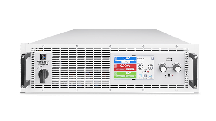
For system integrators, panel builders, procurement teams, and electrical engineers, selecting a programmable DC power supply is not just a voltage-and-current exercise. The supply must fit the rack, AC infrastructure, DUT operating envelope, automation architecture, safety concept, cooling plan, and expansion roadmap. The EA-PS 10000 3U family provides a broad 5 kW, 10 kW, and 15 kW platform in a 19-inch, 3U chassis, with models from 60 V to 2000 V and up to 510 A.
This guide turns those specifications into an RFQ-ready selection process. TPS can supply this product class, help compare ratings, support integration and customized project requirements, and coordinate solutions for global B2B programs.
EA-PS 10000 3U platform: dense programmable DC power
The family combines a wide output matrix with a common mechanical and control platform. Nominal ratings span 0-60 V to 0-2000 V, 0-20 A to 0-510 A, and 5 kW, 10 kW, or 15 kW. This lets engineering teams select the closest useful operating envelope instead of overbuying voltage or accepting inadequate current at the DUT’s real operating point.
The units regulate in constant-voltage, constant-current, constant-power, and internal-resistance modes. The specified full-scale load regulation is no more than 0.05% in CV, 0.1% in CC, and 0.3% in CP. Typical dynamic figures include voltage rise and fall times of up to 10 ms in CV and current rise and fall times of up to 2 ms in CC. These are useful screening values, but the RFQ should still state the required transition, load, cable, and measurement conditions.
A 5-inch capacitive color touchscreen, two rotary encoders, user profiles, data logging to a USB stick, and a graph view support commissioning at the rack. Remote operation is available through built-in isolated USB and 100 Mbit Ethernet, a galvanically isolated 15-pin analog interface, and optional fieldbus modules.
5 / 10 / 15 kW
60-2000 V
up to 510 A
19-inch, 3U
Select from the DUT operating envelope, not the headline rating
1. Define maximum operating voltage and fault margin
Start with the DUT’s continuous range, start-up behavior, expected transients, and applicable test procedure. Available voltage classes are 60, 80, 200, 360, 500, 750, 1000, 1500, and, in the 15 kW class, 2000 V. Higher voltage is not automatically better: it changes insulation, terminals, cabling, clearances, and the available current. Procurement should request the exact model rather than a generic “15 kW supply.”
2. Check current at every critical operating point
For low-voltage, high-current applications, ratings reach 510 A on the 60 V and 80 V, 15 kW models. At higher voltages, current decreases: the 15 kW matrix includes 210 A at 200 V, 120 A at 360 V, 90 A at 500 V, 60 A at 750 V, 40 A at 1000 V, 30 A at 1500 V, and 20 A at 2000 V. Plot the DUT’s required points against both voltage and current boundaries. A wattage-only comparison can conceal an unusable operating region.
3. Verify the facility supply before freezing the BOM
The standard AC input has two operating ranges: 208 V ±10%, three-phase, and 380-480 V ±10%, three-phase, at 45-65 Hz. At 208 V, DC output is derated to 3 kW, 6 kW, or 9 kW for the nominal 5 kW, 10 kW, or 15 kW classes. Power factor is approximately 0.99; specified inrush at 400 V is approximately 40 A per phase. The RFQ must therefore name site voltage, frequency, protective device concept, and available feeder capacity.
Model matrix for supplier screening
The following compact matrix groups the available ratings. Product links lead to representative TPS Shop configurations; TPS can help confirm the correct SKU, interface option, accessories, and project quantity before order release.
| Power | Available V/A combinations | Example product |
|---|---|---|
| 5 kW | 60/170, 80/170, 200/70, 360/40, 500/30, 750/20 | EA-PS 10200-70 3U |
| 10 kW | 60/340, 80/340, 200/140, 360/80, 500/60, 750/40, 1000/30, 1500/20 | EA-PS 10500-60 3U |
| 15 kW | 60/510, 80/510, 200/210, 360/120, 500/90, 750/60, 1000/40, 1500/30, 2000/20 | EA-PS 12000-20 3U |
Other useful selection points include the 60 V / 510 A model, 80 V / 510 A model, 360 V / 120 A model, and 1000 V / 40 A model.
Control interfaces for automated test and production systems
Built-in, galvanically isolated USB and Ethernet provide a practical baseline for remote control. The rear USB host supports data acquisition. Optional isolated interfaces include CAN, CANopen, RS-232, Modbus TCP, Profinet, Profibus, EtherCAT, and Ethernet. The correct option should be frozen with the controls architecture because retrofitting affects qualification and commissioning.
The isolated 15-pin analog interface can use switchable 0-10 V or 0-5 V signal ranges. Inputs cover voltage, current, power, resistance, remote control, output on/off, and resistance mode; outputs include voltage and current monitoring, alarms, reference voltage, DC status, and CV/CC mode. For PLC-based rigs, define fail-safe states, output enable logic, interlocks, and scaling in the interface control document.
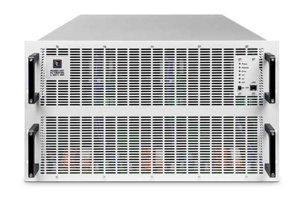
Teams developing compact bench systems may also compare the EA-PS 3200-02 C desktop supply or EA-PSI 9000 DT desktop platform. For high-power rack architectures, TPS can evaluate the 3U platform alongside the EA-PU 10000 6U programmable DC supply.
Rack, AC, DC, and thermal integration
Mechanical and airflow planning
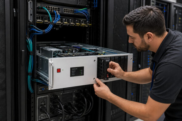
The enclosure is 19 inches wide, 3U high, and 668 mm deep; total depth is at least 777 mm. Weight is approximately 18 kg for 5 kW, 25.4 kg for 10 kW, and 32.8 kg for 15 kW. Do not qualify a cabinet from U-height alone. Check usable rail depth, rear cable bend radius, terminal guards, support rails, lifting method, and service access.
Cooling is forced front-to-rear with temperature-controlled fans. Operating temperature is 0-50 °C, humidity up to 80% non-condensing, altitude up to 2000 m, and pollution degree 2. Cabinet doors must not restrict airflow; exhaust recirculation and neighboring heat sources need review. For complete rack projects, TPS can coordinate power integration with a Sentinel-Y 42U 19-inch cabinet or a 6U 19-inch chassis integration concept.
DC conductors, sensing, and grounding
High-current variants demand short, low-inductance conductors or busbars, correct torque, touch protection, and a documented thermal rise calculation. Remote sense compensates up to 5% of nominal voltage, but sense wiring must be routed and fused according to the equipment documentation. The DC output is isolated from AC and not internally grounded; the project safety assessment must define permissible pole-to-PE potentials. Series operation carries model-specific isolation restrictions and does not support master-slave control or remote sensing.
Unobstructed cool-air intake
Exhaust, terminals, bend radius
3-phase AC, DC bars, PE, sense
Ethernet/USB/analog/fieldbus
Safety, EMC, protection, and reliability evidence
The manual specifies safety conformity to EN/IEC/UL 61010-1, CSA C22.2 No. 61010-1, and BS EN 61010-1. EMC references include EN 55011 Class B, CISPR 11 Class B, FCC 47 CFR Part 15B Class B, and EN 61326-1 with immunity tests. The construction is protection class I and IP20. Confirm the exact declarations, regional marks, production revision, and required test documentation with TPS during the RFQ; standards references alone do not replace project-level compliance assessment.
Adjustable protections include OVP, OCP, and OPP from 0-110% of nominal rating, plus overtemperature shutdown. The platform also reports power-fail, Share Bus, and other operating alarms. For a machine or test rack, define whether an alarm triggers a controlled DUT state, contactor opening, discharge path, data capture, or operator intervention.
SEMI F47 ride-through functionality is documented for qualifying units and firmware, with restrictions. It is unavailable while low-line derating is active and reduces maximum power when enabled. Semiconductor projects should include firmware, power envelope, voltage-sag profile, and acceptance test in the RFQ rather than assuming feature availability from the series name.
Application fit and scalable power architectures
Typical use cases include automotive component validation, inverter and converter development, battery charging tests, industrial electronics burn-in, aerospace and defense subsystems, semiconductor equipment, and production end-of-line stations. The decisive question is whether the required operating points, dynamics, ripple, control path, and fault response fit the application.
Up to 64 units from the compatible Series 10000 ecosystem can be combined for parallel operation through master-slave and Share Bus connections. Mixed power classes are supported under documented firmware conditions; the highest-power unit should be selected as master to avoid an unexpectedly reduced aggregate rating. Loss of a slave connection shuts down the DC outputs as a safety response. These details should be engineered before rack wiring is released.
If the test process must absorb energy rather than only source it, compare a dedicated EA-PUL 10000 regenerative DC load or a bidirectional power architecture for cell formation. TPS can help define whether the project needs a source, load, bidirectional stage, or coordinated multi-instrument system.
What TPS needs for a fast, technically useful RFQ
- DUT voltage/current operating points, transient requirements, and target power class.
- AC site voltage, frequency, feeder limitation, region, and installation environment.
- Rack depth, airflow, ambient temperature, altitude, cable exit, and service constraints.
- Required remote interface, software environment, analog scaling, interlocks, and logging.
- Protection thresholds, discharge concept, grounding, isolation, and compliance documents.
- Single-unit or parallel architecture, quantity, delivery schedule, commissioning, and customization scope.
With these inputs, TPS can support model selection, equivalent solution review, interface and rack integration, customized engineering discussions, and commercial coordination for global B2B customers. Start with the EA-PS 10500-60 3U product page or send the complete requirement for a project-level recommendation.
FAQ
What output range does the EA-PS 10000 3U family cover?
The documented matrix covers 5, 10, and 15 kW models, 60-2000 V, and up to 510 A. Not every voltage is offered at every power/current combination, so select from the model matrix.
Can a 15 kW unit deliver 15 kW from a 208 V three-phase supply?
No. At 208 V ±10% three-phase input, the 15 kW class is specified with DC output derating to 9 kW. A 380-480 V three-phase supply is required for the nominal power envelope.
Which remote-control interfaces are available?
Isolated USB, 100 Mbit Ethernet, and a 15-pin analog interface are built in. Optional modules include CAN, CANopen, RS-232, Modbus TCP, Profinet, Profibus, EtherCAT, and Ethernet.
Can multiple units be paralleled?
Yes. Up to 64 compatible Series 10000 units can be used in a master-slave/Share Bus architecture, subject to model, firmware, wiring, and configuration requirements.
How should buyers request a quote from TPS?
Provide the DUT envelope, AC supply, interface, rack conditions, protection and compliance needs, quantity, destination, and schedule. TPS can then confirm the model or propose an equivalent, integrated, or customized solution. Contact TPS for programmable power support.