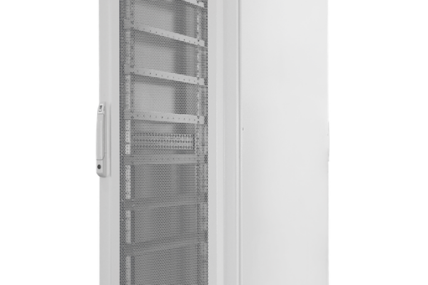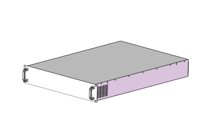
For system integrators, panel builders, procurement teams, and electrical engineers: a 2U enclosure is not merely a metal box. It is the mechanical reference for rack fit, cooling, service access, cable routing, and the commercial risk behind an RFQ. The TPS 2U 19-inch chassis provides a practical platform for compact power electronics, test equipment, control assemblies, and project-specific rack systems.
Why a 2U 19-inch chassis matters at the bottom of the funnel
At the supplier-selection stage, the decisive question is whether the enclosure can become a controlled mechanical platform for the complete assembly. The height designation alone does not answer that. Engineers must reconcile panel geometry, rail interfaces, component envelopes, airflow, connector zones, grounding, and service access. Procurement must also understand what is standard, what is configurable, and what information is required before price and lead time can be dependable.
The TPS 2U chassis product page provides the commercial entry point for a compact 19-inch enclosure. TPS can also support project selection, mechanical adaptation, component integration discussions, and equivalent chassis solutions for global B2B programs. That capability is useful when a project needs more than a catalogue enclosure: for example, dedicated cutouts, a defined surface finish, internal mounting features, or coordination with a power conversion architecture.
482.6 mm overall width, 2U panel height, rack-hole alignment
Heat map, intake, exhaust, pressure drop, fan concept
AC/DC, signal, communications, safety, service access
Drawings, quantity, finish, modifications, validation scope
Confirmed specifications from the product documentation
The supplied dimensional documentation identifies the 2U ordering reference as BJ9900002. It defines a 482.6 mm overall width and a 670.5 mm overall case-body depth. The nominal product overview rounds the chassis envelope to W482.6 × D671 mm. The front-panel height is 88.1 mm. These values should be used as the baseline for rack planning; project drawings should still be checked before release because usable internal space depends on panel thicknesses, fasteners, handles, ventilation, and any custom internal structure.
| Item | 2U value | RFQ relevance |
|---|---|---|
| Ordering reference | BJ9900002 | Identifies the base 2U configuration |
| Overall width W1 | 482.6 mm (±0.8) | Standard 19-inch rack interface |
| Mounting-hole spacing W2 | 465 mm (±0.3) | Front-rail alignment |
| Case-body width W3 | 449 mm (±0.8) | Component and ducting envelope |
| Case-body depth D1 / overall depth D2 | 666 mm (±0.8) / 670.5 mm (±0.8) | Cabinet depth, rear clearance, cable bend radius |
| Panel height H1 | 88.1 mm (±0.2) | 2U rack occupation and adjacent clearance |
| Materials | Sheet steel, aluminum, galvanized plate | Mechanical, finishing, and grounding review |
Surface treatment is component-specific: the front, side, top, and bottom plates are powder-coated; the rear plate can be powder-coated or nickel-plated; and handles use colorless oxidation. The documented color for the front, side, top, and bottom plates is RAL 7035 or customized. Supply includes the front plate, side plates, top and bottom plates, and handles.
The documentation does not state IP rating, load capacity, shock or vibration class, EMC performance, UL/CE status, flammability rating, grounding hardware, or a completed-system thermal rating. These should therefore be specified and verified at project level rather than assumed from the enclosure format.
Selection logic for engineering, integration, and procurement
System integrators: begin with the complete architecture
Map every power module, controller, contactor, protection device, busbar, terminal, fan, filter, and harness. Then reserve zones for insulation distances, airflow, maintenance tools, and cable bends. A 2U format is attractive when rack density matters, but density only creates value when the complete assembly remains buildable and serviceable.
Panel builders: verify the cabinet interface
Confirm rail position, support method, total installed depth, rear-door clearance, and cable entry. A deep chassis should not rely on the front flange alone without a reviewed support concept. The overall depth of approximately 670.5 mm must be checked against the target cabinet, connector protrusion, and required bend radius. For larger integrated systems, compare the architecture with a 42U 19-inch power cabinet or a 24U power-integration platform.
Procurement: separate the base chassis from project scope
Request a clear bill of supply, drawing revision, finish, quantity, packaging, documentation, and change-control assumptions. Ask whether holes, labels, PEM hardware, brackets, fans, filters, wiring, and assembly are included or quoted separately. This makes offers comparable and prevents a low base price from hiding later engineering and integration costs.
Rack, depth, component map
Power, signals, cooling, service
System-level standards and tests
Drawings, scope, quantity, schedule
Integration, cooling, and installation considerations
Thermal planning should start with watts lost inside the enclosure, not equipment nameplate power. Create a loss budget for converters, semiconductors, magnetics, resistors, relays, and auxiliary supplies. Define allowable inlet temperature and component junction or case limits. From there, determine whether passive openings are sufficient or whether forced air, directed ducts, filters, fan monitoring, or an external heat-transfer path is required. Vent patterns shown in representative drawings are not a substitute for a project-specific airflow assessment.
Connector placement must support safe assembly and maintenance. Separate hazardous voltage, protective earth, low-voltage control, and communication zones as required by the completed equipment design. Check creepage, clearance, conductor bend radius, fuse access, and strain relief. If the chassis will host programmable power equipment, the integration approach can be compared with TPS content on compact programmable DC power and regenerative DC-load systems.
Grounding is a system decision. Coated panels may require defined bonding points, coating removal around contacts, serrated hardware, or dedicated bonding conductors. Verify continuity after final assembly and after any finishing operation. EMC behavior likewise depends on seams, apertures, cable shields, filters, gasket strategy, and internal layout; it cannot be inferred from “metal enclosure” alone.
Customization and TPS project support
The documented RAL 7035 or customized color option is useful for machine families, laboratory systems, and OEM programs. Beyond color, RFQ discussions can address front- and rear-panel machining, ventilation geometry, mounting plates, brackets, handles, labeling, connector apertures, and mechanical interfaces. Feasibility, tolerances, minimum quantities, and validation requirements should be agreed before release.
TPS has capability in 19-inch chassis and cabinet solutions, power electronics, and project-level integration. This allows the chassis conversation to include what will actually be installed. For example, a compact auxiliary rail can be evaluated alongside the TPS030 30-130W DIN-rail supply, while higher transient demand may point to a DIN-rail power supply with power boost. High-power rack projects can use TPS experience from 6U 19-inch power-supply integration and 4U rack integration as architectural references.
2U 19-inch dimensional baseline
Cutouts, finish, brackets, airflow features
Power, thermal, interface, serviceability review
RFQ coordination for OEM and integration programs
To confirm a standard purchase, visit the 2U chassis shop listing. For modifications, alternative configurations, or a coordinated rack solution, contact TPS through the 19-inch cabinets and chassis solution page.
RFQ checklist and supplier-evaluation questions
- Mechanical: 2U, rack standard, cabinet depth, front/rear support, internal keep-out zones, target mass, handles, and service clearances.
- Component layout: dimensioned CAD or component list, heat sources, busbars, PCBs, DIN rails, connectors, fans, filters, and harness routes.
- Interfaces: connector types, panel locations, protective earth, cable shielding, emergency or safety circuits, and communication ports.
- Thermal: internal losses, ambient range, altitude, airflow direction, acoustic constraints, filter maintenance, and fan redundancy.
- Finish: RAL color, rear-panel treatment, marking, labels, corrosion environment, and cosmetic acceptance criteria.
- Compliance: target countries, completed-equipment standards, test plan, documentation, material declarations, and responsibility matrix.
- Commercial: prototype and series quantities, target schedule, packaging, spares, forecast, change control, and requested quotation validity.
A strong supplier response should identify assumptions and exceptions rather than silently pricing an undefined build. Ask for the drawing revision behind the quotation and confirm who owns thermal verification, EMC testing, safety evaluation, and system certification. TPS can help translate these requirements into a chassis selection or an equivalent project-specific solution.
Where the 2U chassis fits
Typical candidates include compact AC/DC or DC/DC assemblies, control and monitoring units, test interfaces, battery-cycling auxiliaries, communication gateways, laboratory power subsystems, and OEM rack electronics. A 2U platform is particularly relevant when front-panel density and rack utilization matter, provided the thermal and service envelope remains realistic. For bidirectional power architectures, review TPS guidance on AC/DC bidirectional modules for cell formation or the 750V bidirectional power-module platform.
Interfaces, switching, data acquisition auxiliaries
Controllers, communication, protection, I/O
Conversion, distribution, monitoring
Repeatable rack platform with project-specific panels
Next step: send TPS your rack constraints, component list, heat-loss estimate, connector map, finish requirement, quantities, and delivery target. Contact TPS for chassis selection and solution consulting, or use the TPS 2U chassis page to review the base product.
Frequently asked questions
What are the confirmed dimensions of the TPS 2U chassis?
The documented overall width is 482.6 mm, overall case-body depth is 670.5 mm, and panel height is 88.1 mm. The overview states W482.6 × D671 mm. Confirm the released drawing for project integration.
Can the chassis color be customized?
Yes. The documentation lists RAL 7035 or customization for the front, side, top, and bottom plates. State the exact RAL color, texture, gloss, marking, and acceptance criteria in the RFQ.
Is certification included?
The supplied chassis document does not declare specific UL, CE, IP, EMC, shock, or vibration certification. Applicable requirements must be defined for the completed equipment and confirmed in the quotation and validation plan.
What should I send for a custom quotation?
Send component and connector layouts, heat losses, rack and support constraints, cutout drawings, finish, compliance targets, prototype/series quantities, and schedule. TPS can then assess standard, modified, or integrated options.
Can TPS support more than the enclosure?
Yes. TPS can support product selection, equivalent solutions, customization, power-system integration, and engineering consultation for global B2B projects. The exact scope is agreed during RFQ review.