System integrators, panel builders, and procurement teams in the automotive supply chain rarely fail because they lack a harness design. They lose time—and budget—when high amperage test results do not match expectations, triggering repeated connector validation cycles and delaying PPAP or CE marking.
TPS Elektronik’s approach to high amperage power supply integration for wire harness and connector testing built to reduce that risk: pre-validated test power architectures, current cycling capability up to 1008 hours. And close integration with development so that thermal and electrical margins are confirmed before formal compliance testing begins.
1. What is a high amperage power supply for harness and connector testing?
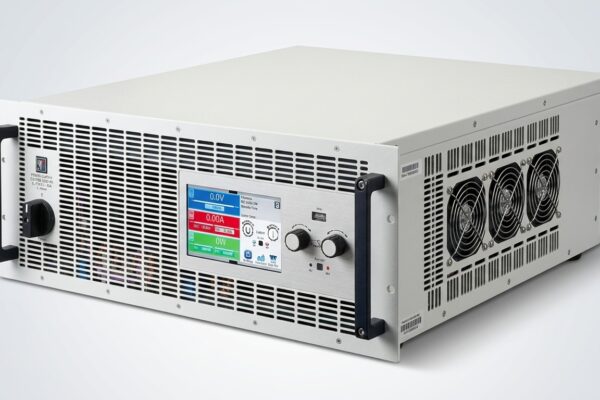
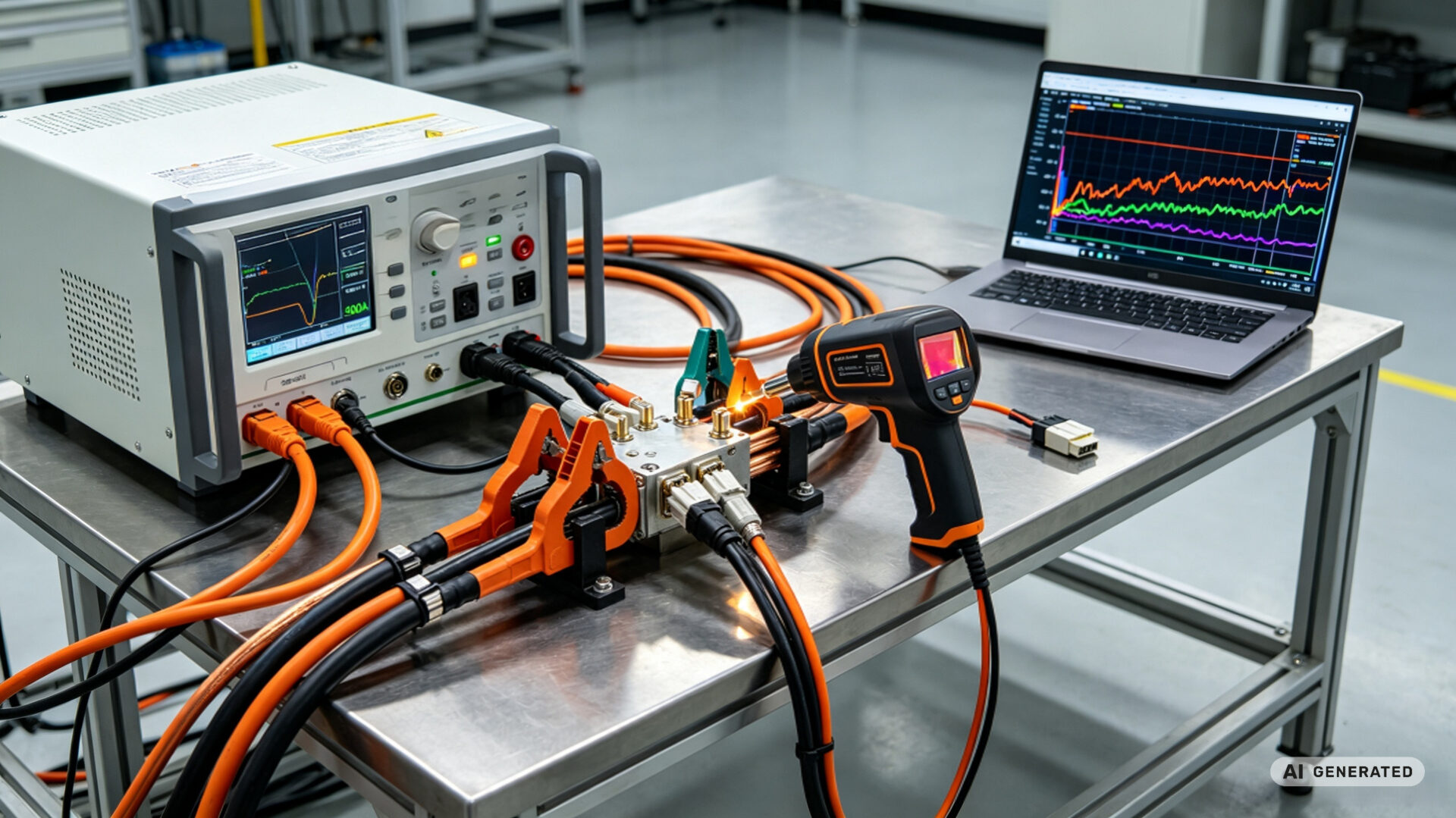
A high amperage power supply for wire harness and connector testing is a programmable DC source designed to deliver continuous currents typically ranging from 100 A to several thousand amperes at low output voltages (2 V to 60 V DC). Unlike general-purpose laboratory power supplies, these units engineered for the specific demands of high current wire harness testing: sustained thermal load, rapid current transitions, and precise measurement of voltage drop across contact interfaces.
In automotive validation, the high amperage harness testing PSU is not simply a power source. It is the instrument that defines whether a connector passes or fails. A current output that drifts by 2% over a 1008-hour test, or a voltage measurement with 10 mV of noise. Which can shift a temperature rise result by several Kelvin—enough to turn a compliant design into a non-compliant one.
Discuss your high amperage test power requirements →
1.1 Key specifications that determine test validity
When specifying a wire harness test power supply, five parameters directly affect test validity:
- Continuous current capability at low voltage: The PSU must sustain rated current at the actual test voltage (often 12 V, 24 V, or 48 V DC), not just at open-circuit voltage. Derating curves must checked at ambient temperatures inside the test chamber.
- Current regulation accuracy: For harness temperature rise test PSU applications, current stability better than ±0.5% required to distinguish connector self-heating from PSU ripple.
- Rise time and transient response: High current harness test system setups for ISO 16750-2 pulse testing require current rise times in the millisecond range. Standard bench supplies with 100 ms slew rates cannot reproduce load dump or inrush profiles.
- Remote sensing and voltage drop measurement: Four-wire Kelvin sensing is mandatory for connector testing power applications, where the voltage drop across a 0.5 mΩ contact must resolved at high current.
- Parallel and master-slave operation: For currents beyond 500 A, modular PSUs with active current sharing allow scalable output without sacrificing regulation.
1.2 Why a standard lab PSU fails at high amperage
A 300 W bench supply rated for 10 A cannot validate a 200 A busbar joint. The failure modes are predictable: output capacitor ESR limits transient current, cable voltage drop consumes headroom, and thermal drift shifts the setpoint. The result is a test that measures the PSU’s limitations rather than the connector’s performance. For automotive connector test power, this distinction is critical. A false pass delays market entry, and a false fail triggers unnecessary design changes.
TPS’s engineering resources on element and material technology and element testing laboratories reflect this system-level view of test power.
2. Why high amperage testing matters for automotive safety compliance
Automotive electrical safety is not defined by a single test. It emerges from the interaction of connector design, wire gauge, insulation material, and the test power source used to validate them. When a high amperage cable testing regime poorly instrumented, the compliance evidence itself becomes unreliable.
2.1 LV214 and USCAR-2: current cycling and temperature rise
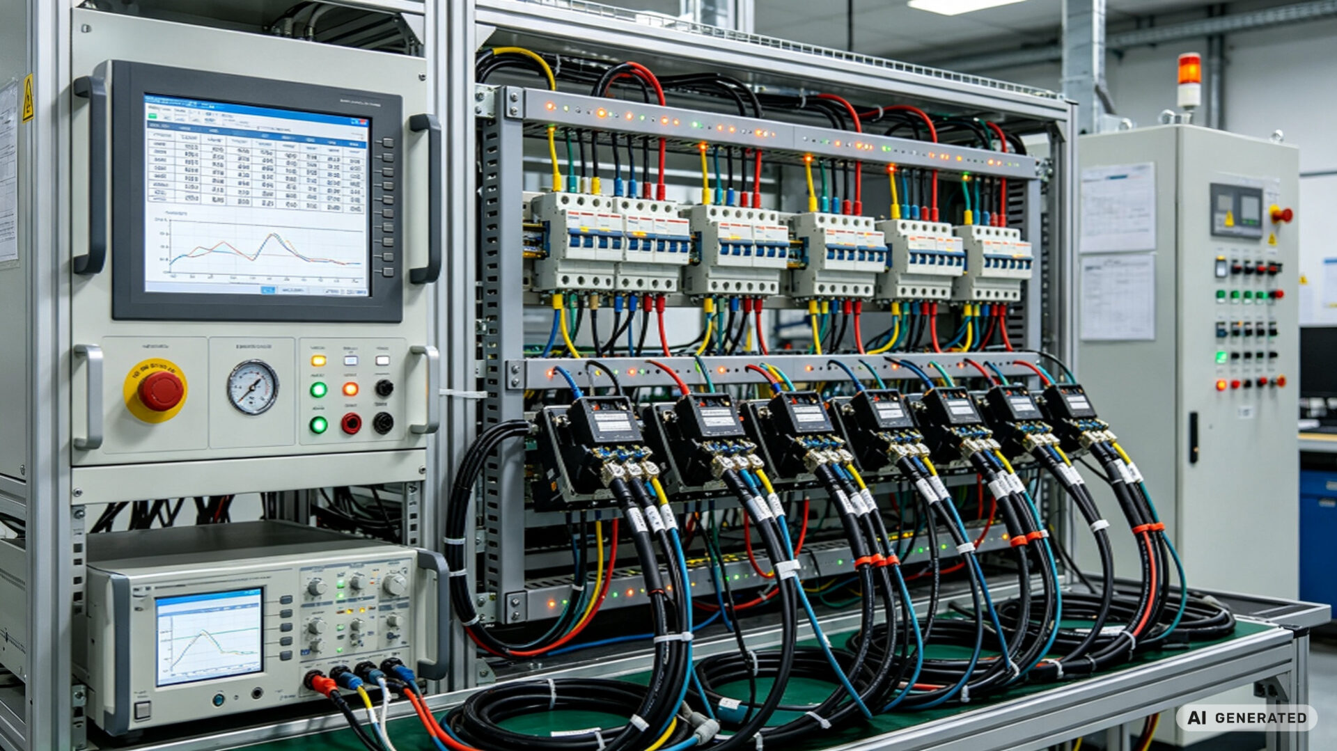
LV214 (the Volkswagen/Audi/Porsche/SEAT/Skoda joint standard) and SAE/USCAR-2 define the core electrical validation requirements for automotive connectors. Both standards require high current wire harness testing under controlled conditions:
- LV214 TG12 (current heating, derating): The connector must carry a specified current without exceeding a temperature rise limit (typically 30 K for 0.35 mm² and 0.50 mm² conductors). The test method follows DIN EN 60512-5-1. Which specifies current-carrying capacity measurement at room temperature without exceeding a defined temperature rise.
- USCAR-2 Test Sequence C (current cycling): 1008 cycles at 1 hour per cycle, with test currents of 11.0 A for 0.35/0.50 mm² terminals. Terminal temperature must remain below 55 °C, and contact resistance limits (30 mΩ for power terminals) must be maintained throughout.
- USCAR-2 voltage drop: Maximum millivolt drop of 50 mV across mated connectors under specified current.
Each of these requirements translates into specific demands on the high amperage power supply. The PSU must hold current within a tolerance tight enough that the measured temperature rise reflects the connector, not the source. It must log voltage drop continuously for 1008 hours without drift. And it must transition between current levels cleanly enough to reproduce the cycling profile.
2.2 ISO 16750-2 and ECE R10: electrical loads and EMC
ISO 16750-2:2023 defines the electrical load profiles that automotive electronic systems must withstand. Which including overvoltage, reverse polarity, and load dump. The standard explicitly notes that electrical loads can vary due to the electrical impedance of the vehicle wiring harness and connection system. A high current harness test system used to validate ISO 16750-2 profiles must therefore deliver not only steady-state current but also the transient waveforms defined by the standard.
For EMC compliance under ECE R10, the latest revision (R10.07, in force since June 2025) extends the immunity frequency range up to 6 GHz and updates transient immunity test methods to reference ISO 7637-2:2011 for pulses 1–3. While ECE R10 testing is distinct from harness current-carrying validation, the automotive electrical test PSU used in R10 test benches must meet similar current capability and transient response requirements.
TPS’s experience with automotive compliance documented in the quality assurance customer case and the metal testing and compliance guide.
3. Critical test applications powered by high amperage PSUs
The high amperage power supply is the backbone of several distinct validation workflows. Each imposes different requirements on current profile, measurement precision, and thermal management.
3.1 Temperature rise testing (harness temperature rise test PSU)
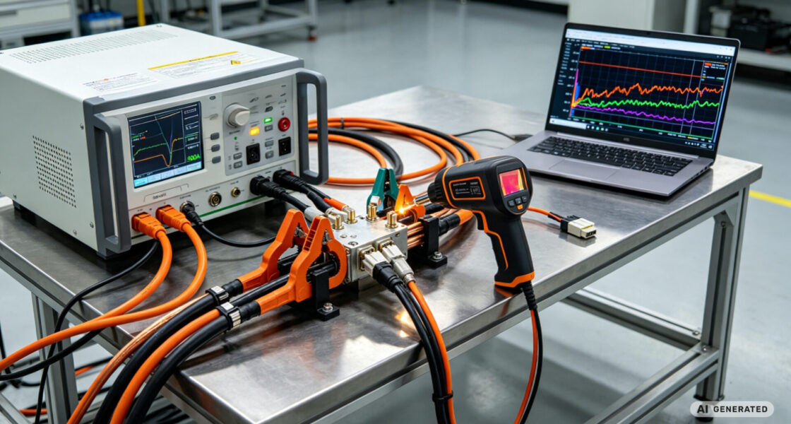
Temperature rise testing measures how much a connector or terminal heats above ambient when carrying its rated current. The test is deceptively simple: apply current, wait for thermal equilibrium, measure temperature. The difficulty lies in the power source. A harness temperature rise test PSU must maintain current within ±1% while the connector’s resistance changes with temperature. A positive feedback loop that a voltage-controlled supply cannot manage. Constant-current mode with remote sensing is mandatory.
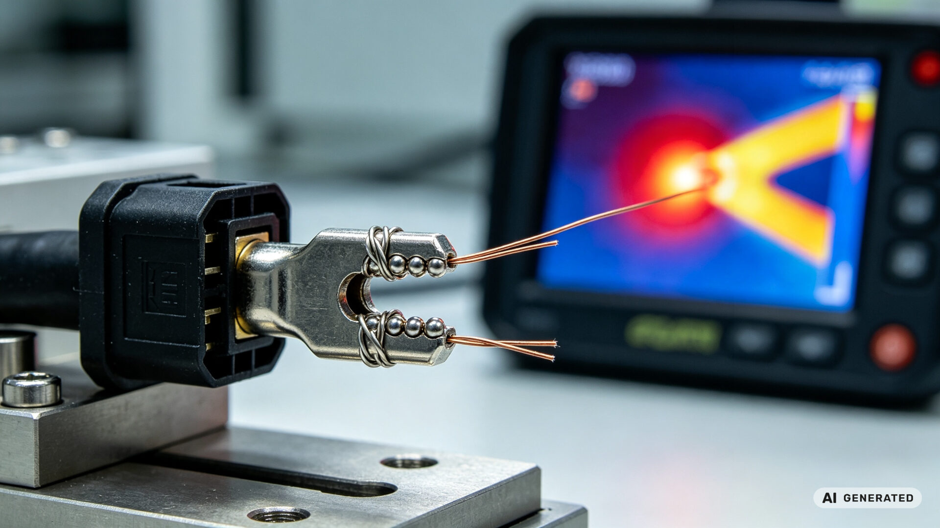
The measurement side is equally demanding. DIN EN 60512-5-1 requires ambient temperature to measured at a defined distance (typically 50 mm) from the hottest point. And the temperature rise calculation is based on the difference between terminal surface temperature and local ambient. Any PSU-induced ripple or current drift introduces thermal noise that broadens the uncertainty band of the result.
3.2 Current cycling and aging validation
Wire harness aging test power regimes subject connectors to repeated current-on/current-off cycles that simulate real-world thermal expansion and contraction. USCAR-2’s 1008-cycle requirement is the reference: one cycle per hour, with current applied for a defined on-time and then removed. Over 1008 hours, the connector experiences cumulative degradation mechanisms—stress relaxation, oxidation, and micro-motion fretting—that only reveal themselves under sustained high-current operation.
For high current wire harness testing of this duration, the PSU must operate unattended for weeks. Protection features—over-temperature shutdown, current limit foldback, and remote interlock. Which are not optional. Data logging must capture current, voltage, and temperature at intervals fine enough to resolve degradation trends, typically once per minute or better.
TPS supports long-duration validation through its material testing and compliance case study and the supply chain optimization guide.
3.3 Voltage drop and contact resistance measurement
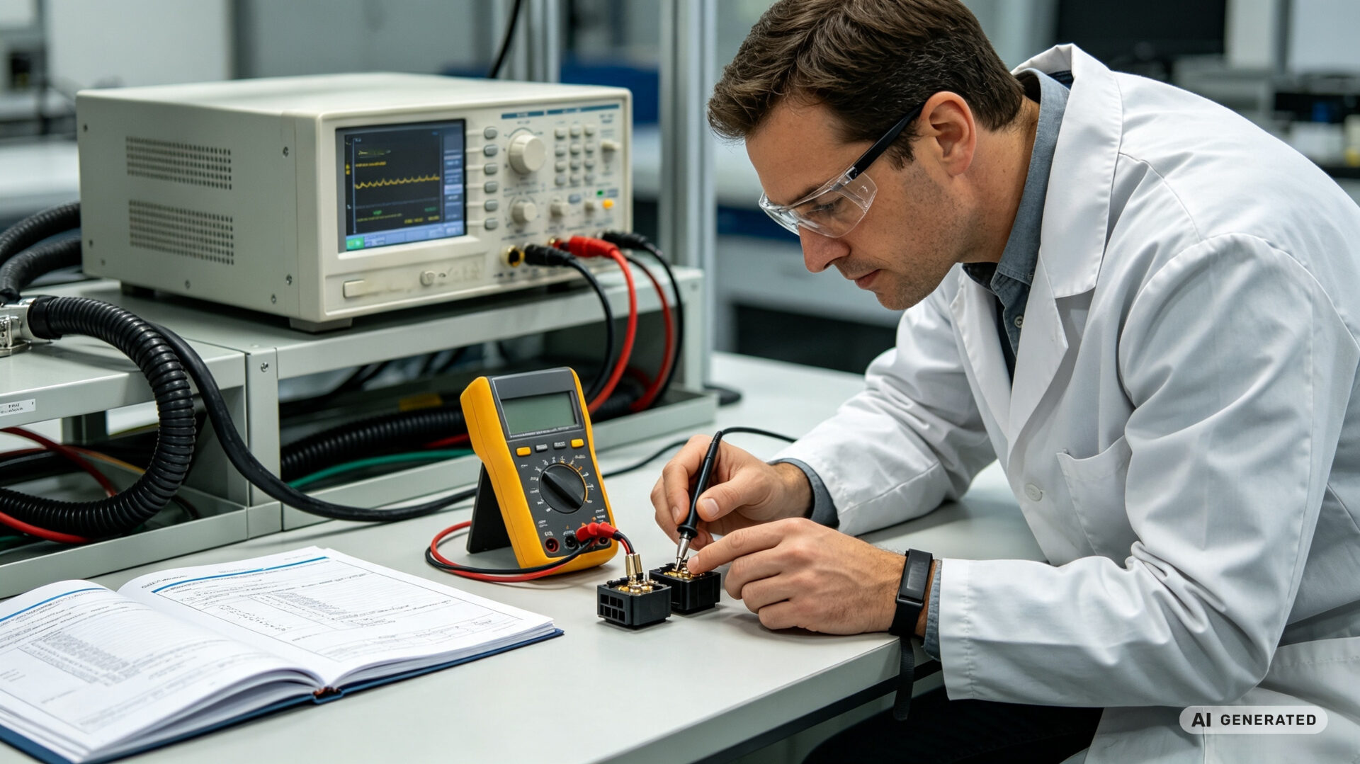
Cable testing high amperage often requires measuring the voltage drop across a connector interface at the rated current. For a 50 A load on a 2 mΩ contact, the expected drop is 100 mV. Resolving a 5 mV change—the threshold that indicates contact degradation. Which requires a measurement system with < 1 mV noise. The connector validation power supply contributes to this noise budget through its output ripple and load regulation.
Four-wire Kelvin sensing at the connector terminals eliminates cable resistance from the measurement. The PSU must provide a stable current while the nanovoltmeter or precision DMM samples the voltage. Some test setups alternate between high-current and low-current measurement phases. Which requiring the PSU to switch between levels without overshoot that could damage the contact interface.
For related validation workflows, see the quality control sample generator case study.
4. How to select a high amperage test power supply
Selecting a wire harness test power supply for automotive validation is a specification exercise, not a catalog lookup. The following framework applies to both in-house test benches and outsourced laboratory validation.
- Define the current profile first: Steady-state current, peak current, rise time, and duty cycle. A 200 A continuous requirement with 10 ms rise time is a different PSU class than a 200 A continuous requirement with 1 s rise time.
- Calculate cable and connection losses: At 500 A, a 1 m copper cable with 0.1 mΩ resistance drops 50 mV and dissipates 25 W. The PSU’s voltage headroom must account for this.
- Verify remote sensing bandwidth: Kelvin sense leads must be rated for the PSU’s common-mode voltage and must not introduce noise. Twisted pairs with shielding are standard.
- Plan for thermal management: A PSU operating at 80% of rated current in a 40 °C test chamber derates further. Specify PSUs with adequate margin or active cooling.
- Confirm data interface and logging: For high current harness test system integration, the PSU must expose current and voltage measurements over LAN, USB, or CAN, with sample rates compatible with the degradation mechanisms being monitored.
TPS’s AI-driven cost reduction and simulation approach can be applied to test power sizing, reducing the risk of over-specifying or under-specifying the PSU.
5. How TPS Elektronik supports high amperage test readiness
TPS Elektronik operates at the intersection of EMS production, test system integration, and global market access. For system integrators and panel builders working on automotive harness and connector validation. This means access to automotive electrical test PSU configurations that are validated against the same standards the end customer will apply.
TPS’s global sales partner model provides structured support from production readiness through regional rollout. For high amperage test benches, this translates into:
- PSU selection and rack integration: Matching current capability, sensing architecture, and thermal design to the specific test standard (LV214, USCAR-2, ISO 16750-2).
- Pre-compliance validation: Running temperature rise and current cycling profiles on prototype connectors before formal laboratory submission, using the element testing laboratory approach.
- Documentation and compliance support: Preparing test reports that reference the correct clauses of LV214, USCAR-2, and DIN EN 60512-5-1 for CE marking and OEM submission.
- Supply chain integration: Ensuring that the PSUs, cables, connectors, and measurement instruments are available across US, EU, and China production sites.
This integrated approach detailed in the global sales partner electronics 2026 guide and the sales playbook for CE mark readiness.
For a customer-facing example of how TPS handles compliance-driven projects, see the global sales partner compliance market entry case study.