System integrators, panel builders, OEMs, and procurement teams rarely struggle to source individual electronic components. The greater challenge is integrating hardware, firmware, communication interfaces, mechanical constraints, and compliance requirements into a system that can move efficiently from prototype to series production.
TPS Elektronik provides integrated development services covering embedded hardware and firmware development, communication protocol integration—including CAN, TCP/IP, Modbus, and serial interfaces—EMC-aware PCB design, mechanical integration, testing support, and preparation for series production.
1. Why Integrated Development Matters
Electronics development extends well beyond schematic design. Hardware architecture, firmware behavior, communication interfaces, EMC and safety requirements, mechanical integration, and production constraints must ultimately operate as one system.
For system integrators and procurement teams, the central question is therefore whether a supplier can deliver a clearly defined and manufacturable system while supporting the applicable compliance process—not simply individual parts of the design.
Developing hardware, firmware, and communication interfaces independently can create scope and integration gaps. A PCB may operate as intended while firmware diagnostics remain incomplete. A CAN interface may function during development, but the validation approach may not reflect production test requirements. Similarly, a power supply can meet its electrical targets while later EMC testing identifies issues that require PCB or filtering changes.
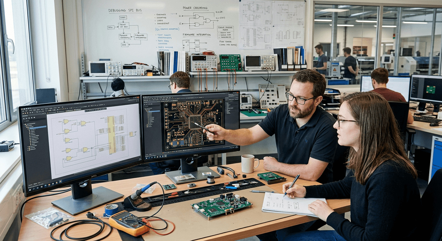
An integrated development approach can address these dependencies earlier in the project:
- Architecture before detailed design: Hardware/software partitioning, communication protocols, component selection, and system interfaces can be aligned with technical and commercial requirements.
- EMC, thermal, and mechanical considerations before layout completion: These constraints can be incorporated during schematic and PCB development rather than addressed only after prototype testing.
- Documentation alongside development: Test procedures, manufacturing documentation, and compliance-related records can be prepared as the design matures.
For industrial projects, the objective is not simply to develop an STM32-based controller, FPGA implementation, CAN interface, or power stage in isolation. These elements must operate together and support the transition from engineering prototype to a reproducible production design.
Related TPS resources include custom power supply development and buck-boost converter design.
2. Embedded Hardware Engineering: From Power Electronics to PCB Design
TPS Elektronik’s hardware development capabilities cover low-power embedded electronics as well as high-power industrial systems. The engineering process considers electrical performance together with component selection, manufacturability, thermal behavior, mechanical constraints, and applicable compliance requirements.
2.1 Power Electronics Development
TPS develops single- and three-phase power supplies, DC/DC converters, rectifiers, and inverter-based systems. Typical power levels range from several hundred watts to several hundred kilowatts, depending on the application. Target applications include industrial power supplies, battery test systems, PV inverters, and energy storage systems.
Engineering activities include:
- Selection and application of power semiconductors, including MOSFETs, IGBTs, SiC, and GaN devices.
- Design of magnetic components such as transformers and inductors, taking electrical and thermal requirements into account.
- Analog sensing circuits for current, voltage, and temperature measurement.
- Integration of relays, contactors, circuit breakers, and other switching or protection devices.
These elements interact closely. Semiconductor selection, switching frequency, magnetics, PCB layout, thermal management, sensing, and protection architecture can all influence efficiency, electromagnetic behavior, reliability, and mechanical design.
2.2 PCB Design and Layout
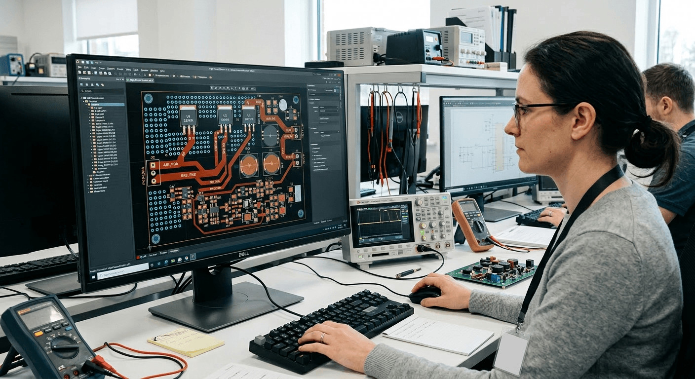
TPS uses Altium Designer and Cadence Allegro for schematic capture and PCB layout. EMC, thermal, electrical, and mechanical constraints are considered during the design process, particularly for mixed-signal boards, high-power layouts, and densely integrated embedded systems.
EMC-aware PCB design may include attention to current return paths, grounding, component placement, filtering, switching loops, interface routing, and separation of sensitive and noisy circuit areas.
Mechanical development is supported using SolidWorks and AutoCAD. Coordinating PCB geometry with enclosures, connectors, mounting points, cooling concepts, and cable routing is particularly relevant for panel builders and system integrators requiring assemblies that must fit into an existing mechanical environment.
For examples of related development work, see the custom power supply design case study and battery test system development.
3. Firmware and Embedded Software: MCU, FPGA, and Control Logic
Embedded hardware depends on firmware for control, diagnostics, communication, monitoring, and fault handling. TPS develops embedded software for microcontroller- and FPGA-based systems, with the software architecture considered alongside the underlying hardware.
3.1 MCU Firmware Development
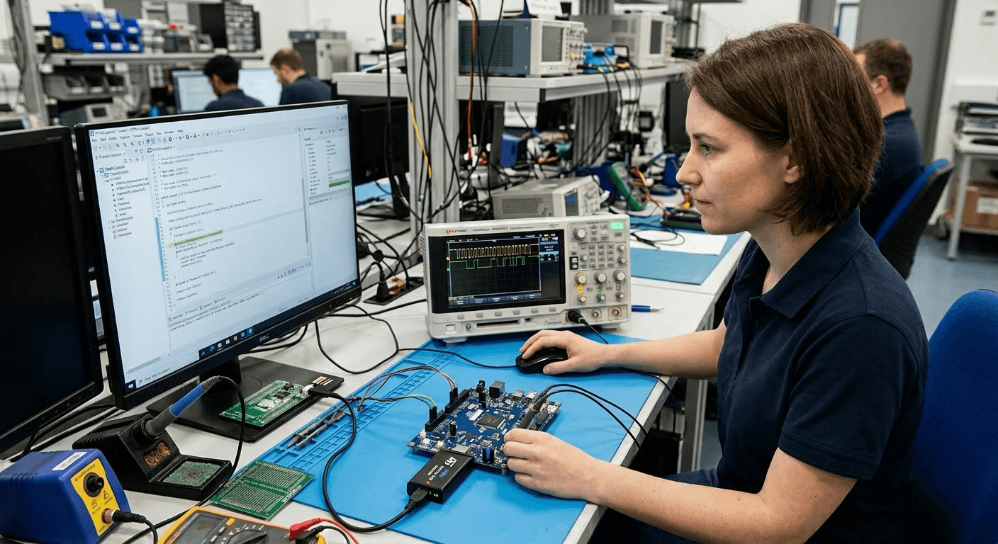
TPS works with STM32, AVR, and other ARM-based microcontrollers. Development can cover low-level peripheral drivers, state machines, real-time control functions, communication interfaces, diagnostics, and application-layer software.
Firmware architecture can also account for maintainability, testing, and field-update requirements where these are part of the system specification.
3.2 FPGA and CPLD Design
For applications requiring deterministic timing, high-speed processing, parallel operations, or application-specific I/O handling, TPS develops FPGA and CPLD implementations using VHDL or Verilog.
Typical applications include motor control, signal processing, timing-critical functions, and custom communication interfaces.
3.3 Control Algorithms and Diagnostics
Control algorithms can be implemented for systems such as power converters, battery management systems (BMS), and motion-control applications.
Diagnostics and fault handling are considered as part of the system architecture. Depending on the application, firmware may need to detect abnormal operating conditions, report diagnostic information, execute defined responses, and place the system into an appropriate operating state.
For related information, see the medical device software development guide and PCB design for medical devices.
4. Communication Protocols: CAN, TCP/IP, Modbus, and Custom Interfaces
Industrial, automotive, and embedded systems often depend on several communication layers. Successful integration requires both appropriate hardware interfaces and firmware that handles data exchange, diagnostics, timing, error conditions, and interoperability with other equipment.
TPS integrates established communication interfaces and can develop application-specific protocol implementations where standard protocols do not meet the system requirements.
4.1 CAN Bus Development: From Hardware Integration to Diagnostics
CAN is widely used in automotive and industrial control systems because it provides robust multi-node communication in electrically demanding environments.
CAN development can include:
- Integration of CAN transceivers with STM32, AVR, and other microcontrollers.
- Firmware support for CAN 2.0B and CAN FD.
- Integration of higher-layer protocols such as CANopen and J1939.
- Development of CAN-enabled controller boards for prototyping or production.
- Test and diagnostic functions for interface validation.
- OBD-II/CAN integration for applicable automotive diagnostic and telematics applications.
A CAN implementation therefore involves more than selecting a transceiver. Termination, topology, physical-layer behavior, message handling, timing, diagnostics, and application-level communication must be considered together.
4.2 TCP/IP and Modbus for Industrial Automation
Ethernet-based communication is increasingly important for industrial controllers, monitoring systems, and connected equipment.
TPS development can include:
- Embedded TCP/IP stacks, including lwIP and application-specific implementations.
- Modbus TCP for communication with PLCs, SCADA systems, and industrial controllers.
- Network interfaces for remote monitoring and device management.
- Application-layer communication built on TCP/IP where required by the system architecture.
TCP/IP comprises a suite of networking protocols rather than a single interface. IP provides network addressing and packet routing, while TCP provides connection-oriented, reliable transport. Embedded implementation must also account for resource constraints, error handling, connection management, and the requirements of the target application.
4.3 Serial Interfaces: RS-232, RS-485, RS-422, USB, and I²C/SPI
Legacy equipment and device-level communication frequently require serial interfaces. TPS develops systems using RS-232, RS-485, RS-422, SPI, I²C, and USB.
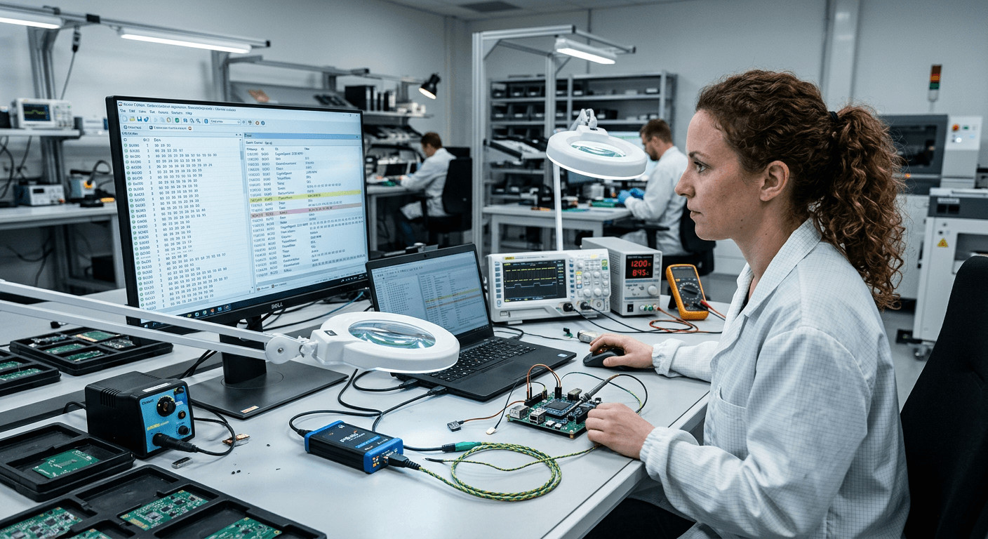
This can include USB-to-serial bridging, integration of legacy RS-232 equipment, multi-drop RS-485 communication, and board-level interfaces between processors, sensors, converters, and peripheral devices.
Where established protocols do not meet the application’s functional requirements, custom communication protocols can also be implemented.
For an example of combined PCB and software development, see the PCB design and software development case study.
5. EMC and Safety: Considering Compliance from the Start
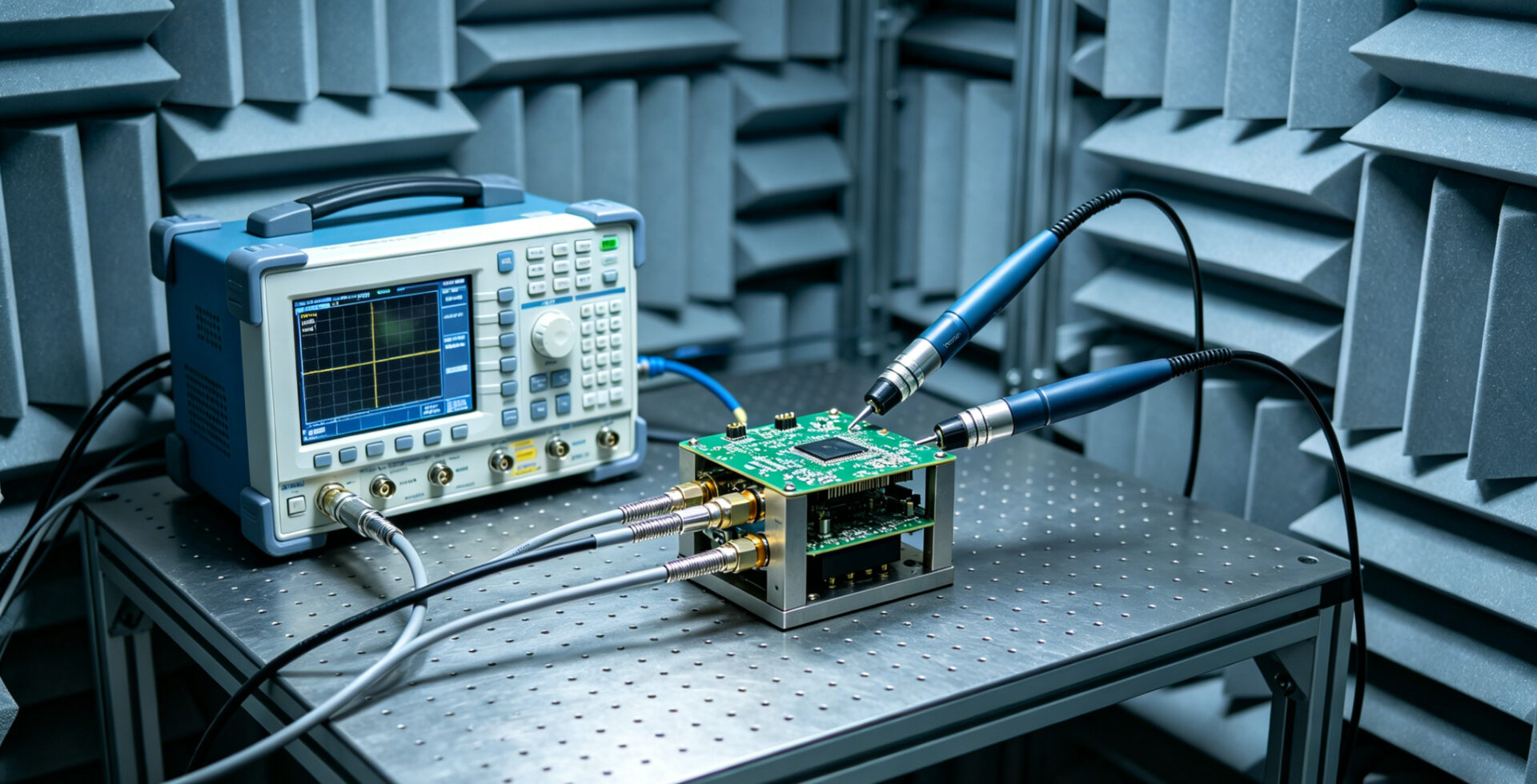
EMC and safety requirements can influence circuit architecture, PCB layout, filtering, grounding, shielding, component selection, enclosure design, and firmware behavior. Addressing these requirements during development can help identify potential issues before formal testing.
5.1 EMC Design and Testing
TPS incorporates electromagnetic compatibility considerations during schematic development and PCB layout. Depending on the application, this may include:
- Grounding and return-path design.
- Input and output filtering.
- Shielding concepts.
- Component placement.
- Switching-loop optimization.
- Interface protection and filtering.
- Separation of sensitive and high-noise circuit areas.
TPS supports EMC pre-compliance activities and can coordinate formal compliance testing with accredited laboratories where required.
Applicable EMC requirements depend on the product, intended environment, market, and regulatory framework. These requirements should therefore be identified during the specification phase rather than assumed from a generic product category.
5.2 Safety Requirements for Automotive and Industrial Electronics
Safety and regulatory requirements vary significantly by application and target market.
For automotive projects, relevant requirements may include ECE R10 for electromagnetic compatibility and ISO 26262 where functional safety applies. U.S. vehicle applications may also be subject to applicable Federal Motor Vehicle Safety Standards (FMVSS).
For industrial systems, relevant IEC, UL, and European requirements depend on the equipment type, intended use, and target market. Standards such as IEC 61010 or IEC 61508 may be relevant to specific applications, but applicability must be determined for the individual project.
Considering these requirements during system architecture and design can support the later compliance process and may reduce the likelihood of extensive modifications following prototype or pre-compliance testing.
External references include the ISO 26262 overview and IEC information on EMC.
6. Development Workflow: From Concept to Series Readiness
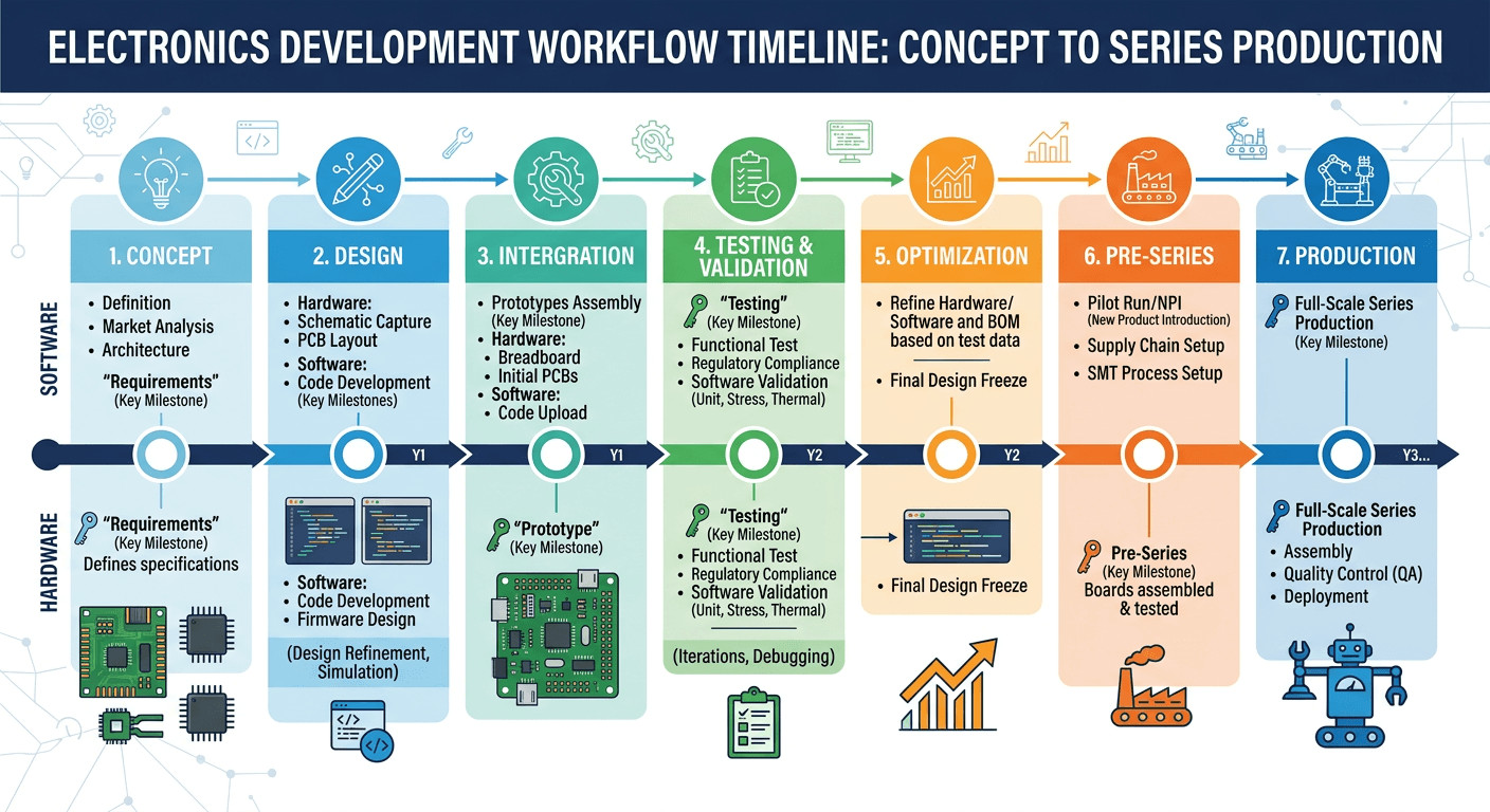
A structured development process helps coordinate electrical, firmware, mechanical, test, and compliance activities. TPS uses a phased approach that can be adapted to the technical scope and production requirements of the project.
6.1 Concept and Requirements Definition
Development begins with clarification of functional requirements, performance targets, electrical interfaces, communication protocols, environmental conditions, mechanical constraints, production quantities, and applicable compliance requirements.
The resulting system specification provides a technical basis for architecture decisions, project planning, and quotation.
6.2 Design and Prototyping
Schematic capture, PCB layout, firmware development, and mechanical design can proceed in parallel once the system architecture and interfaces have been defined.
Functional prototypes are then used to evaluate critical electrical functions, firmware behavior, communication interfaces, thermal performance, and system integration.
6.3 Testing and Compliance Preparation
Depending on the project requirements, prototype validation may include:
- Electrical and functional testing.
- Thermal characterization.
- Communication-interface testing.
- EMC pre-compliance testing.
- Safety-related analysis where applicable.
Test results provide the basis for design iterations before the project proceeds to pre-series or production preparation.
6.4 Series Readiness and Production Transfer
Once the design has reached the required maturity, manufacturing documentation, test procedures, test fixtures, and quality-related documentation can be prepared for production.
TPS can also support the transition into series production through its electronics manufacturing services (EMS). Keeping development and manufacturing within a coordinated process can simplify design-data transfer and allow production feedback to be incorporated into the final design.
Related project examples include buck-boost converter design and circuit breaker retrofit and panel modernization.
7. When Integrated TPS Development Services May Be Appropriate
TPS Elektronik’s development services are intended for projects that require coordination across several engineering disciplines rather than an isolated PCB layout or firmware task.
Relevant capabilities include:
- Integrated hardware and firmware development: Hardware architecture, interfaces, firmware, and control functions can be developed within a coordinated engineering process.
- Communication protocol integration: Support includes CAN, CAN FD, CANopen, J1939, TCP/IP, Modbus, serial interfaces, and application-specific protocols.
- EMC-aware development: EMC considerations can be incorporated into schematic design, PCB layout, mechanical integration, and prototype evaluation.
- Prototype-to-series support: Development can be followed by production preparation and EMS manufacturing.
- Power electronics experience: TPS develops systems ranging from embedded electronics to power-conversion equipment operating at power levels of several hundred kilowatts.
For procurement teams, an integrated approach can simplify technical coordination by reducing the number of interfaces between separate hardware, firmware, mechanical, and manufacturing suppliers.
For engineering teams, it provides a development structure in which PCB design, embedded software, communication interfaces, mechanical integration, testing, and production requirements can be evaluated as parts of the same system.
8. FAQ: Electronics Development Services
What communication protocols can TPS integrate?
TPS integrates CAN 2.0B, CAN FD, CANopen, J1939, TCP/IP, Modbus RTU, Modbus TCP, RS-232, RS-485, RS-422, SPI, I²C, USB, and application-specific communication protocols.
The appropriate interface and protocol depend on factors such as topology, bandwidth, distance, timing requirements, environmental conditions, interoperability, and the existing system architecture.
What is the typical development process for a custom embedded system?
A typical process includes requirements definition, system architecture, schematic and PCB development, firmware development, mechanical integration where required, prototyping, electrical and functional testing, thermal evaluation, EMC pre-compliance activities, and preparation for series production.
The exact process depends on the technical scope, application, production requirements, and applicable regulatory or certification requirements.
Does TPS support both prototype development and series production?
Yes. TPS can support development through prototyping and subsequently provide electronics manufacturing services for series production.
Maintaining continuity between development and manufacturing can simplify production transfer because design data, test requirements, component information, and manufacturing constraints can be addressed within a coordinated process.
How is EMC addressed during development?
EMC considerations are incorporated during schematic development and PCB layout through measures such as grounding and return-path design, filtering, shielding concepts, component placement, interface protection, and management of switching-current loops.
Prototype-stage EMC pre-compliance testing can then be used to identify potential issues before formal testing. Where required, TPS can coordinate formal compliance testing with accredited laboratories.
What safety standards are considered for automotive and industrial projects?
The applicable standards depend on the product, application, target market, and regulatory requirements.
For automotive electronics, relevant requirements may include ISO 26262 for functional safety and ECE R10 for EMC. Applicable U.S. vehicle requirements may include FMVSS provisions.
For industrial applications, standards such as IEC 61010 and IEC 61508, together with applicable European and UL requirements, may be relevant depending on the equipment and intended use. Standard applicability should therefore be established during the requirements and compliance-planning phase.