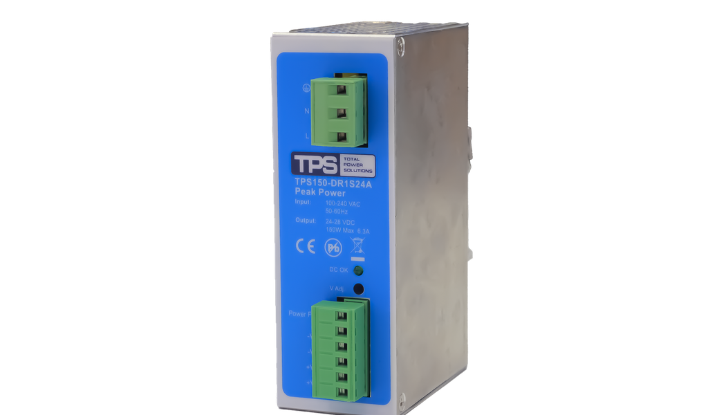
For system integrators, panel builders, procurement teams, and electrical engineers: the TPS150-DR1S24A is a 150 W DIN rail power supply designed for dependable 24 VDC control power, with adjustable 24–28 VDC output, 6.3 A rated current, and a 170% power boost for up to 10 seconds. This page translates the datasheet into a practical supplier-selection and RFQ checklist so you can assess electrical fit, cabinet integration, compliance evidence, and project support before release.
Review the TPS150-DR1S24A product page or contact TPS for DIN rail power supply selection and an RFQ.
Where the TPS150-DR1S24A fits in a 24 VDC control system
The TPS150-DR1S24A is positioned for industrial automation, LED lighting, and telecommunications equipment that needs a compact, enclosed DIN rail AC/DC supply. Its nominal 150 W output and 6.3 A current rating align with PLC racks, industrial controllers, sensors, relays, HMIs, communications devices, and other 24 VDC loads. The adjustable 24–28 VDC range is useful when the designer needs to compensate for cable voltage drop or align the bus with an approved load window.
The buying decision should start with the continuous load, not the headline wattage. Add the steady-state current of all loads, apply realistic simultaneity, include future expansion, and confirm the worst operating temperature. Loads with solenoids, motors, capacitive input stages, or other start-up peaks also require a time-current review. The unit’s temporary boost can help, but it is not a substitute for checking peak amplitude, duration, repetition rate, wiring drop, and protective-device coordination.
For procurement, the exact ordering reference matters: TPS150-DR1S24A, article number 901004402. TPS can support the product itself as well as equivalent DIN rail power supply selection, engineering consultation, integration questions, and project-level supply for global B2B customers.
85–264 VAC, 47–63 Hz
or 120–370 VDC
DIN rail AC/DC conversion
Convection cooled
24–28 VDC adjustable
6.3 A / 150 W
Key electrical and environmental specifications
| Parameter | Datasheet value | RFQ relevance |
|---|---|---|
| Input | 85–264 VAC, 47–63 Hz; 120–370 VDC | Confirm actual mains range, upstream protection, and DC-input use. |
| Power factor / leakage | >0.96; <0.5 mA at 264 VAC, 50/60 Hz | Relevant to system power quality and leakage-current budgeting. |
| Output | 24–28 VDC adjustable, 6.3 A, 150 W | Check every load at the selected setpoint; current and power limits still apply. |
| Dynamic capacity | 170% boost for 10 seconds, auto recovery | Match against peak current, duration, and repetition. |
| Hold-up / ripple | 20 ms at full load and 230 VAC; ripple/noise <1% of output voltage | Review controller ride-through and sensitive-load tolerance. |
| Efficiency | 93% at 220 VAC and maximum load | Supports cabinet heat estimation; use actual operating point for final calculation. |
| Environment | 0–70°C; derating from 50–70°C; 5–95% RH non-condensing; storage −25–85°C; altitude 3000 m | Check enclosure temperature, airflow, altitude conditions, and condensation risk. |
| Mounting / conductors | Vertical on TS 35/7.5 or TS 35/15; AWG 26–14 (0.15–2.5 mm²), 300 VAC terminals | Validate rail layout, conductor sizing, ferrules, torque, and local code. |
These values are strong screening inputs, but they do not replace a project-specific review. Dimensions, terminal torque, spacing, inrush current, short-circuit behavior, exact protection curves, parallel/series operation, and current certificate files are not fully established by the supplied summary datasheet. Include them in the RFQ when they affect design release.
How to evaluate the 170% power boost
At rated output, 170% corresponds to a temporary theoretical power level of about 255 W. For a 24 V bus, that is roughly 10.6 A; however, this arithmetic is only a screening aid. The actual available voltage and current during a transient depend on the operating point and protection behavior. Ask TPS to confirm the intended load profile rather than designing solely from the percentage.
Four boost checks before approval
- Amplitude: measure or obtain the maximum start current at the lowest expected bus voltage.
- Duration: ensure the event stays inside the specified 10-second boost window.
- Repetition: disclose the duty cycle; repeated starts can create a different thermal condition from a single event.
- Downstream behavior: confirm cable drop, branch protection, load undervoltage thresholds, and controller reset tolerance.
If the load has a short, high peak, the boost may reduce the need to oversize the supply. If the overload is sustained, frequent, uncertain, or occurs above 50°C, selecting a higher continuous rating is usually the more robust engineering path. TPS can compare this 150 W model with the broader TPS100–320W Peak DR+ power-boost range.
Design around 150 W / 6.3 A and applicable thermal derating.
Up to 170% for 10 seconds, with automatic recovery.
Recalculate and consider a higher continuous power class.
DIN rail integration, wiring, and thermal design
The datasheet specifies vertical installation on 35 mm DIN rail, either TS 35/7.5 or TS 35/15. Preserve the orientation because convection cooling relies on the expected air path. Do not treat a nominal 0–70°C rating as permission to deliver full power across that entire range: output derating begins at 50°C. The relevant temperature is the local ambient around the supply inside the energized enclosure, not the room temperature outside it.
Thermal review
At the stated 93% efficiency and 150 W output, a first-pass loss estimate is approximately 11.3 W. This is an engineering estimate derived from the datasheet efficiency, not an additional guaranteed specification. Add losses from neighboring devices, consider solar gain and enclosure sealing, and verify the final design under worst-case line, load, and ambient conditions. Keep ventilation paths clear and request required clearance information from TPS.
Wiring and voltage setting
The terminal range is AWG 26–14 (0.15–2.5 mm²). Conductor selection must still account for current, length, temperature, grouping, voltage drop, protective-device coordination, and applicable installation rules. Use suitable ferrules where required, follow the confirmed tightening torque, and document the output-voltage setting during panel test. Raising the output toward 28 V may improve remote voltage, but only if every connected load is approved for that voltage.
Panel builders should also define the upstream disconnect and protective device, PE and grounding concept, separation from noisy conductors, and branch protection on the DC side. For broader system architecture, TPS can combine DIN rail selection with enclosure and power-integration expertise such as the Sentinel-Y 42U power cabinet approach.
Vertical TS 35 rail
Clear convection path
Above 50°C
Size and protect circuits
Voltage, load, and temperature
Reliability, protection, safety, and EMC review
The datasheet lists convection cooling, overtemperature protection, overvoltage protection, overload protection, automatic recovery, a five-year warranty, and demonstrated MTBF above 350,000 hours at full load and 25°C ambient. MTBF is a statistical reliability indicator under stated conditions; it is not a service-life guarantee. Procurement should consider warranty terms, operating stress, replacement strategy, and supply continuity alongside the numerical MTBF.
The supplied document states CE compliance with the Low Voltage Directive 2014/35/EU and EMC Directive 2014/30/EU, and lists UL 508, UL 60950-1, and EN 60950-1. Because standards, editions, transition rules, product categories, and certificate scopes change, the project team should request current declarations and applicable certificates for the exact article number and target market. This is particularly important where a component approval must support a panel or machine certification. Treat datasheet markings as screening information, not a substitute for the controlled compliance file.
The document also states electromagnetic susceptibility testing to IEC 801 parts 2–6, Level 3. For an RFQ, specify the actual equipment environment, required immunity/emissions standards, cable lengths, grounding, enclosure type, and any sector-specific requirements. TPS can then confirm available evidence or recommend an equivalent solution whose documentation better fits the project.
Selection logic: when this 150 W model is the right choice
Select TPS150-DR1S24A when
- the system uses a 24 VDC bus and continuous demand remains within 150 W and 6.3 A after derating;
- temporary start-up peaks can be validated against the 170%/10-second boost;
- wide-range AC input, or the documented high-voltage DC input range, suits the architecture;
- vertical DIN rail mounting and convection cooling fit the enclosure;
- the project can validate current compliance documents and detailed integration data before release.
Consider another rating or architecture when
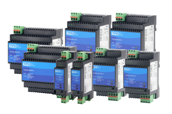
Continuous load, ambient temperature, expansion margin, or repeated peaks exceed the available envelope. A lower-power control panel may be better served by the TPS030–130W Pro Series, while larger or more dynamic loads can be assessed against the 100–320 W Peak DR+ family. Bench validation and programmable test sequences may instead call for a programmable desktop DC supply. TPS can help define the correct product class instead of forcing an unsuitable component into the design.
Line, load, peaks, hold-up
Losses, ambient, derating
Rail, clearance, terminals
Current files and scope
Quantity, schedule, support
What to include in your TPS150-DR1S24A RFQ
For a faster, higher-quality technical and commercial response, provide the target quantity and schedule together with the electrical and mechanical context. A useful RFQ package includes:
- input voltage/frequency range and target countries;
- continuous load table, peak current, peak duration, and repetition rate;
- required DC setpoint, permissible ripple, hold-up, and voltage-drop limits;
- enclosure type, maximum internal ambient, altitude, rail orientation, and available space;
- upstream/downstream protection, grounding, cable sizes, and critical loads;
- required declarations, certificates, inspection documents, and acceptance tests;
- prototype, annual volume, delivery location, forecast, and lifecycle expectations.
TPS supports global B2B customers with product selection, equivalent solutions, customization and integration consultation, and project coordination. Start with the TPS150-DR1S24A shop listing for the target item, then use the TPS DIN rail solutions page to request a technical review or quotation. If the exact model is not optimal, TPS can evaluate an appropriately rated alternative.
Move from component search to a qualified RFQ
Send TPS your load profile, cabinet conditions, compliance needs, quantity, and delivery schedule. The response can address both the TPS150-DR1S24A and technically suitable alternatives.
Open the target product | Request DIN rail selection support and a quotation
Frequently asked questions
What is the rated output of the TPS150-DR1S24A?
The datasheet specifies 150 W, 6.3 A, and an adjustable 24–28 VDC output. Confirm the selected setpoint and total load against both current and power limits.
Can the 170% boost be used continuously?
No. It is specified for up to 10 seconds with automatic recovery. Sustained or frequently repeated overloads require a load-profile and thermal review and may justify a larger supply.
Does the supply deliver full power at 70°C?
The operating range is stated as 0–70°C, but derating applies from 50–70°C. Request the derating curve and calculate available output at the actual internal cabinet temperature.
Which compliance documents should procurement request?
Request current declarations and applicable certificate files for article 901004402 and the destination market. Confirm the standard edition, product category, conditions of acceptability, and whether additional equipment-level testing is required.
Can TPS support an equivalent or integrated solution?
Yes. TPS can support selection, equivalent DIN rail products, customization or integration consultation, and project-level supply. Provide the complete operating and commercial requirements in the RFQ.