For system integrators, panel builders, and engineering-focused procurement teams, selecting a power supply for automated test equipment (ATE) involves more than matching voltage, current, and power ratings. Communication interfaces, rack integration, thermal management, system-level EMC, programming performance, and compatibility with the test automation architecture all influence whether a power supply can be integrated effectively into an automated test system.
This guide explains how to evaluate programmable DC power supplies for ATE applications, with a focus on form factor, communication interfaces, power density, electrical performance, and practical system integration.
1. What Is an ATE Power Supply?
An ATE power supply (Automated Test Equipment power supply) is a programmable, remotely controllable DC source designed for integration into automated test sequences. In contrast to power supplies used primarily for manual bench testing, an ATE-oriented power supply typically provides capabilities such as:
- Remote control interfaces, including Ethernet, GPIB, RS-232, or Modbus
- Programmable voltage and current sequencing
- Voltage and current readback
- Protection functions whose status can be monitored by software
- Form factors suitable for rack integration, including 1U to 6U designs
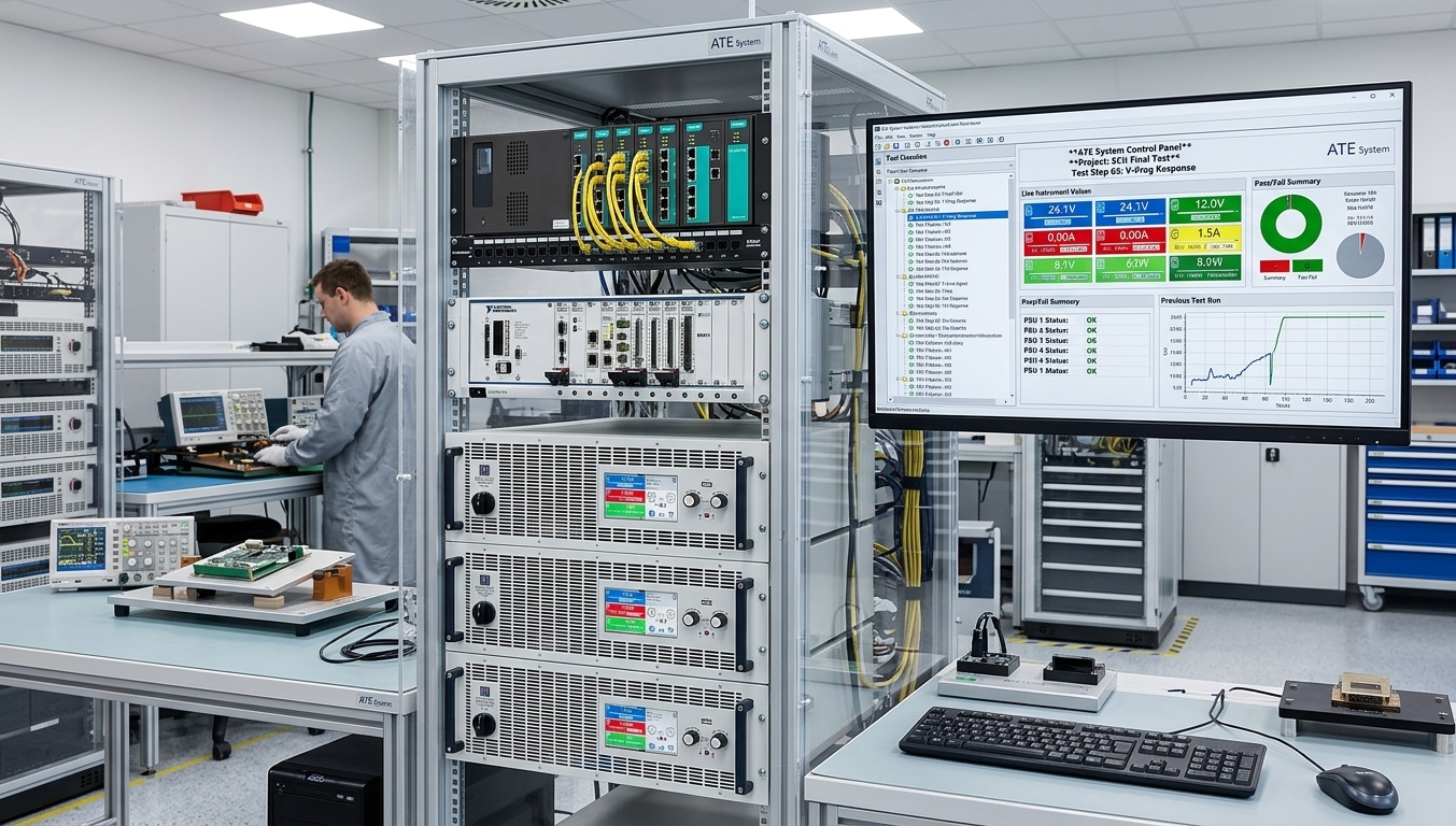
In a typical ATE rack, the power supply operates alongside measurement instruments, switching systems, electronic loads, and other equipment under the control of a test executive or automation environment such as LabVIEW, Python, or C#. The ability to program output levels, execute defined voltage or current sequences, retrieve measurements, and respond to fault conditions without manual intervention is therefore central to the role of a programmable DC power supply in automated testing.
For an overview of specific programmable power supply families, see our programmable power supply options guide.
2. Form Factors: Benchtop, Rack-Mount, and High-Density Designs
The mechanical format of a programmable DC power supply affects rack utilization, cooling, accessibility, and the overall architecture of the test system. The appropriate form factor depends primarily on whether the equipment is intended for development, manual testing, or permanent integration into an automated system.
2.1 Benchtop DC Power Supplies for Development and Validation
A benchtop DC power supply is commonly used for R&D, prototype validation, troubleshooting, and low-volume test stations. These units typically provide a front-panel display and controls for direct operation, together with rear-panel interfaces for remote programming.
This combination is useful during development because engineers can interact with the supply manually while establishing test parameters, then transition to software-controlled operation as the test procedure becomes more automated.
TPS benchtop series include the EA-PSI 9000 DT desktop series and EA-PS 3200-02 C. A broader selection is available in the desktop programmable DC power supply category.
2.2 Rack-Mount Power Supplies for Production Test Systems
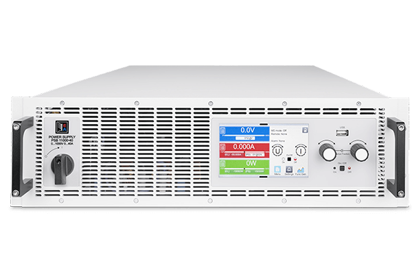
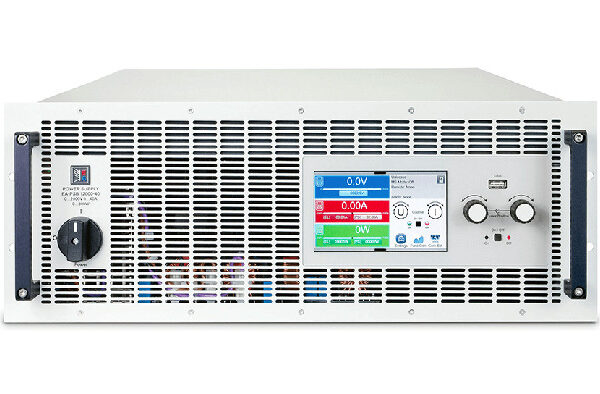
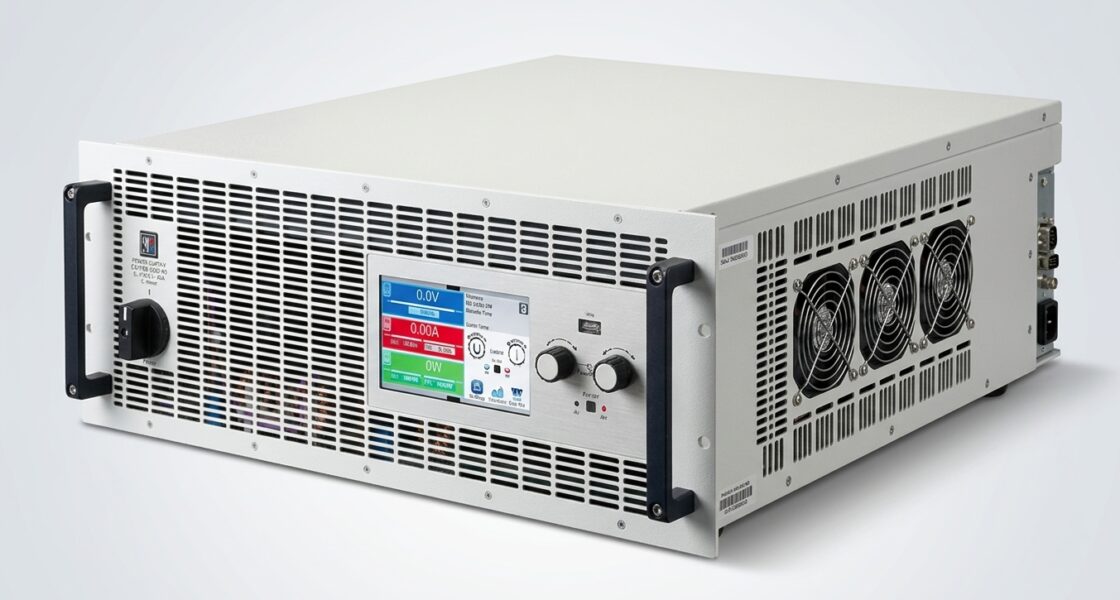
Rack-mount power supplies are generally better suited to permanent ATE installations and production test systems. They are designed for integration into standard 19-inch racks and are commonly available in heights such as 1U, 2U, 3U, 4U, and 6U.
The rack format can support several system-level requirements:
- Efficient use of rack space: Multiple instruments can be arranged vertically within a defined enclosure.
- Controlled airflow: Cooling can be planned at rack level rather than for individual bench instruments.
- Centralized communication: Multiple devices can be connected to common network or control infrastructure.
- Scalable test architectures: Additional power channels or instruments can be integrated as system requirements expand.
When evaluating rack height, the number of available units should not be considered in isolation. Required output power, airflow direction, cable access, serviceability, and the space needed for other ATE instruments should also be included in the rack layout.
TPS rack-mount series are organized by height: 1U programmable DC power, 2U, 3U, 4U, and 6U.
2.3 High-Power-Density Supplies for Space-Constrained Racks
In ATE systems where several instruments compete for limited rack space, power density becomes an important design parameter. A higher power density allows more output power to be installed within a given rack height, which can be useful in compact production test systems or multi-channel configurations.
Higher power density, however, also places greater emphasis on thermal design. Cooling capacity, airflow restrictions, ambient temperature, and the heat generated by adjacent equipment should be evaluated before selecting a high-density unit.
TPS offers high-power programmable solutions, including systems described in the 60 kW programmable DC power supply overview.
For applications where rack height is a primary constraint, see the 1U programmable DC power supply guide and 2U programmable DC power supply guide.
3. Communication Interfaces: Ethernet, GPIB, and System Integration
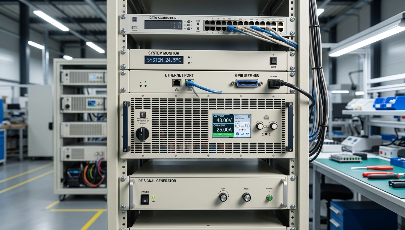
The communication interface determines how the programmable DC power supply connects to the test controller and how easily it can be incorporated into the existing automation architecture. Interface selection should therefore be based on the control system, available software support, required cable distances, and compatibility with existing instruments.
3.1 Ethernet for Modern Test Automation
Ethernet is widely used in modern ATE environments because it supports network-based control over standard infrastructure. Depending on the power supply and its interface implementation, Ethernet connectivity may support functions such as:
- Network connections over cable lengths of up to 100 m for standard copper Ethernet links
- Connection of multiple instruments through network switches
- Protocols such as SCPI over TCP/IP, Modbus TCP, or VXI-11 where supported
- Remote monitoring or browser-based access on models that provide a web interface
Ethernet can simplify integration when the test executive, MES environment, or supervisory system already uses IP-based communication. The specific protocol and command set should nevertheless be verified for the selected power supply rather than assuming that all Ethernet-equipped instruments behave identically.
3.2 GPIB for Legacy Test Systems
GPIB remains relevant in established test installations where existing instruments, software, and test procedures were developed around IEEE-488 communication. In these systems, selecting a GPIB programmable power supply can support integration without requiring a complete redesign of the control architecture.
GPIB also remains supported by established test automation environments such as LabVIEW. For retrofit projects, engineers should verify address configuration, driver availability, command compatibility, and any differences between the replacement power supply and the equipment it replaces.
3.3 Modbus, RS-232, and Other Interfaces
Industrial test systems may also use Modbus RTU, Modbus TCP, RS-232, or manufacturer-specific interfaces. Modbus can be useful where a programmable power supply must communicate with a PLC-based control system, while RS-232 remains suitable for straightforward point-to-point connections.
The preferred interface should be selected according to the wider automation architecture. In addition to the physical interface, engineers should consider command latency, software libraries, driver support, error handling, triggering requirements, and how instrument status will be integrated into the test sequence.
The EA-PSI 9000 DT series provides an example of a programmable power supply family intended for integration with different control environments.
4. Key Specifications: Accuracy, Resolution, Dynamic Performance, and Protection
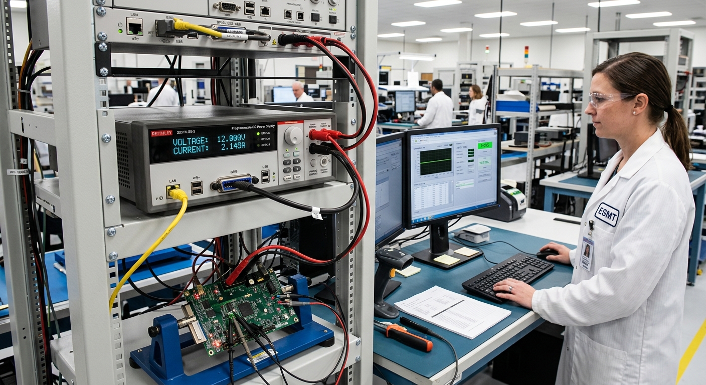
Voltage, current, and total output power define the basic operating range of a programmable DC power supply, but they are not sufficient for evaluating ATE performance. The following parameters should also be compared against the requirements of the test procedure and device under test (DUT).
- Programming accuracy: Determines how closely the actual output corresponds to the programmed setpoint. The required accuracy depends on the allowable supply tolerance of the DUT and the limits used in the test specification.
- Programming resolution: Defines the smallest output increment that can be commanded. Higher resolution can be important when test sequences require small voltage or current steps.
- Readback accuracy: Describes the accuracy of voltage and current measurements returned by the power supply. This matters when readback values are used as part of automated pass/fail criteria or test documentation.
- Slew rate and transient response: Describe different aspects of output dynamics. Slew rate affects how quickly a programmed output can change, while transient response indicates how the supply reacts to load changes. Both can be relevant when testing devices with controlled power-up profiles or dynamic current demand.
- Protection functions: Depending on the model, protection mechanisms may include overvoltage protection (OVP), overcurrent protection (OCP), and overtemperature protection (OTP). For automated systems, the ability to detect and report a protection event through the control interface can support structured fault handling.
- Power density: Indicates how much output power can be accommodated within a given rack height. Higher density can conserve rack space, but it may also increase cooling requirements.
Specification values should always be checked in the documentation for the individual power supply. Requirements such as programming accuracy, interface capability, or dynamic response can vary considerably between product series and operating ranges.
For applications where a 2U format fits the rack architecture, see the 2U programmable DC power supply guide.

5. Integration Considerations: Cabling, Thermal Management, and EMC
Successful ATE integration depends on the complete electrical and mechanical installation, not only on the selected power supply. Cabling, grounding, remote sensing, cooling, and test sequencing should therefore be addressed during system design.
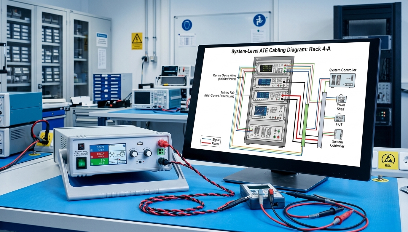
- Output cabling: Select conductor size according to current, allowable voltage drop, cable length, installation conditions, and applicable engineering requirements. High-current connections should be kept as short as practical. Twisted conductors can help reduce loop area and associated electromagnetic coupling.
- Remote sensing: Where supported, remote sense connections can compensate for voltage drop in the output leads by regulating the voltage at the load rather than only at the power supply terminals. This can be particularly relevant for long cable runs or higher-current DUT connections.
- Thermal management: Rack-mounted power supplies commonly use forced-air cooling. Intake and exhaust paths should remain unobstructed, and the total thermal load of the rack should be considered when sizing ventilation or cooling systems.
- EMC and grounding: Programmable power supplies can both generate and be affected by electrical noise. Appropriate grounding, separation of power and signal wiring, shielding where required, and careful cable routing can support system-level EMC performance.
- Test sequencing: Automated measurements should begin only after the programmed supply condition has reached the required state. Depending on the application, this may require defined settling delays, status polling, software interlocks, or synchronized triggering.
These measures are particularly important when small voltage deviations, switching transients, or communication faults could affect test repeatability.
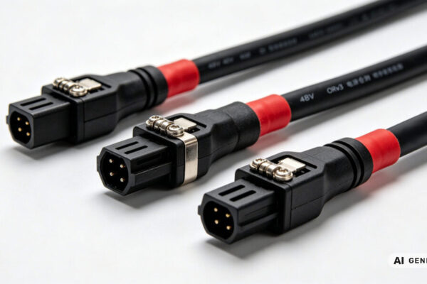
For related system components, see the programmable power accessories category for available rack-mount accessories, control adapters, and cable assemblies.
6. TPS Programmable DC Power Supply Series Overview
TPS Elektronik provides programmable DC power supplies in desktop and rack-mount formats for applications including R&D, automated test systems, and production environments. Selection should be based on the required electrical range, programming performance, communication interface, rack constraints, and system-level integration requirements.
6.1 Desktop Programmable DC Power Supplies
The desktop programmable DC power supply range is intended for applications where front-panel operation remains important alongside remote control. This format can be suitable for development laboratories, prototype validation, service environments, and test stations that combine manual and automated operation.
6.2 1U, 2U, 3U, 4U, and 6U Rack-Mount Series
For automated systems and production test installations, rack-mount programmable power supplies are available in several mechanical formats:
- 1U: 1U series for applications where rack height is tightly constrained
- 2U: 2U series for applications requiring a balance between available rack space and output capability
- 3U: 3U series for systems requiring a larger mechanical and power envelope
- 4U: 4U series for higher-power rack installations
- 6U: 6U series for applications requiring a larger high-power platform
The rack height alone does not determine suitability. Engineers should compare the actual voltage and current operating ranges, available interfaces, cooling requirements, dimensions, and model-specific functions before selecting a unit.
6.3 Accessories for System Integration
System integration may also require rack-mount hardware, cable assemblies, communication adapters, or other accessories. Available options can be found in the programmable power accessories category.
7. FAQ: Programmable DC Power Supplies for ATE
7.1 What communication interfaces are commonly used for ATE power supplies?
Ethernet is widely used in new ATE systems because it can be integrated into standard IP-based networks. GPIB remains relevant in existing test systems built around IEEE-488 instruments. RS-232 and Modbus are also used, particularly in point-to-point or PLC-based automation architectures. The appropriate interface depends on the controller, software environment, installed infrastructure, and compatibility requirements.
7.2 What is the difference between benchtop and rack-mount programmable DC power supplies?
Benchtop supplies are typically optimized for direct interaction during laboratory work and development, with front-panel displays and controls readily accessible to the engineer. Rack-mount supplies are mechanically designed for integration into 19-inch systems and are often operated primarily through remote interfaces in automated test installations.
7.3 Why is power density important in ATE applications?
ATE racks have limited mechanical space, and the power supply must share that space with measurement equipment, electronic loads, switching hardware, controllers, and other instruments. Higher power density can allow more output capability within a given rack height, although the associated cooling requirements must also be considered.
7.4 What is remote sensing, and when is it useful?
Remote sensing uses separate sense connections to measure the voltage closer to the DUT rather than only at the power supply output terminals. Where supported, the power supply can compensate for voltage drop in the output wiring within its specified sense compensation range. This can be useful when cable resistance would otherwise introduce a relevant difference between the programmed voltage and the voltage applied to the DUT.
7.5 How should I choose between 1U, 2U, 3U, or larger rack-mount power supplies?
Start with the required voltage, current, and power range, then compare those requirements with the available rack space and cooling capacity. Interface compatibility, programming performance, service access, cabling, and the number of required power channels should also be considered. A smaller rack height is advantageous only when the selected unit still meets the electrical and thermal requirements of the ATE system.