When an RFQ reaches the shortlist stage, the question is no longer whether a DIN rail power supply is available. The focus shifts to whether the selected unit fits the application, supports brief overload events, aligns with project requirements, and simplifies technical evaluation during procurement.
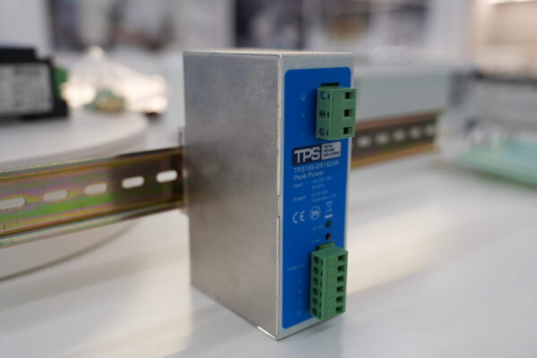
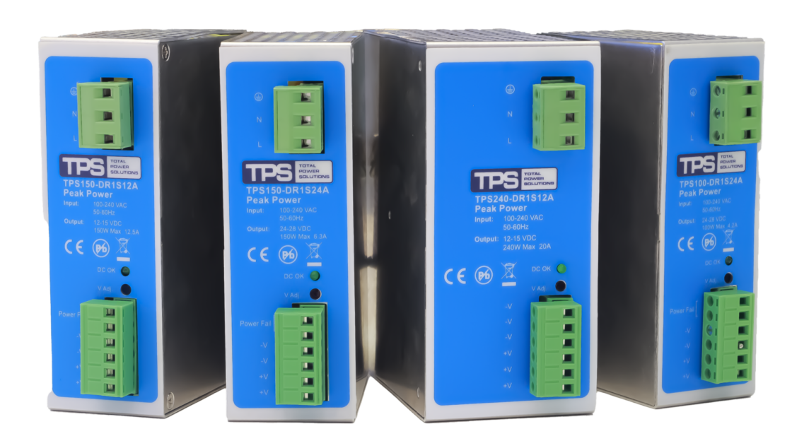
The TPS100–320W Peak DR+ Series is designed for these applications. It offers power ratings from 100 W to 320 W, adjustable 12 V and 24 V output classes, a 170% power boost for up to 10 seconds, convection cooling, and DIN rail mounting for industrial control cabinets.
Beyond the product itself, TPS can support model selection, equivalent solutions, cabinet integration discussions, and technical clarification during the RFQ process.
Why this series matters during RFQ evaluation
At the final supplier evaluation stage, buyers are usually validating a solution for a real control cabinet, industrial machine, telecom installation, or automation subsystem. The decision typically focuses on four practical questions:
- Does the input range match the intended installation?
- Can the power supply handle short-term load peaks?
- Will it integrate cleanly into the control cabinet?
- Can the supplier provide technical support throughout the RFQ process?
According to the specification sheet, the Peak DR+ family offers:
- 85–264 VAC or 120–370 VDC input
- 47–63 Hz operation
- Adjustable 12–15 VDC or 24–28 VDC outputs
- Power factor >0.96
- 20 ms hold-up time at full load (230 VAC)
- Ripple and noise below 1% of output voltage
- 170% power boost for up to 10 seconds with auto-recovery
These are the parameters engineering and procurement teams commonly review when comparing industrial DIN rail power supplies.
12V or 24V
Continuous load
Peak current event
DIN rail fit
Compliance + RFQ
A power supply that appears suitable in a catalogue may still require further evaluation if startup current, thermal conditions, cabinet layout, or documentation requirements are unclear. Reviewing these aspects early can help streamline technical discussions during supplier selection.
170% power boost: what it means
The 170% power boost should not be interpreted as a replacement for proper sizing.
Instead, it provides additional capacity during short-duration load events such as equipment startup or switching transients. Depending on the application, this may help support temporary current peaks while maintaining normal continuous operation.
Model selection
Select the power supply in the following order:
- Output voltage
- Continuous load
- Peak load requirements
- Mechanical dimensions
- Installation environment
For many industrial control systems, 24 V remains the standard control voltage. However, 12 V versions continue to be used in legacy systems, communication equipment, and specialised subsystems.
Engineering teams should determine continuous and transient current requirements, while panel builders should verify available installation space and terminal accessibility. Procurement should confirm that the quoted model exactly matches the required voltage and current rating.
| Application need | Linked TPS model | Output class | Best-fit discussion |
|---|---|---|---|
| Compact 12V loads with moderate current | TPS100-DR1S12A | 12-15V adj., 8A, 96W | Useful when space and modest 12V load demand are the priority. |
| Compact 24V control circuits | TPS100-DR1S24A | 24-28V adj., 4.2A, 100W | A starting point for small panels, signal-level power, and lighter 24V cabinets. |
| Mid-range 12V systems | TPS150-DR1S12A | 12-15V adj., 12.5A, 150W | Suitable when 12V distribution needs more headroom without moving to a larger architecture. |
| Mid-range 24V industrial controls | TPS150-DR1S24A | 24-28V adj., 6.3A, 150W | Often appropriate for machine sections with denser control and I/O requirements. |
| Higher-current 12V branches | TPS240-DR1S12A | 12-15V adj., 20A, 240W | Better when current reserve and stable startup margin matter more than minimal cabinet width. |
| Stronger 24V cabinet power | TPS240-DR1S24A | 24-28V adj., 10A, 240W | A practical choice for busier 24V cabinets with multiple downstream loads. |
| Highest linked 24V power in this brief | TPS320-DR1S24A | 24-28V adj., 12.5A, 320W | Best when panel-level 24V demand is already substantial and power reserve is commercially critical. |
100W Compact controls | 150W Mid-range panels | 240W Higher current | 320W Large 24V demand |
Key specifications
Rather than comparing nameplate power alone, RFQ teams often review the following characteristics:
| Parameter | Series value | Why RFQ teams care |
|---|---|---|
| Input range | 85-264 VAC or 120-370 VDC, automatic | Supports broader installation environments and simplifies global project planning. |
| Frequency | 47-63 Hz | Relevant for international AC systems and documented acceptance criteria. |
| Power factor | >0.96 | Useful when system-level energy and input behavior are part of the review. |
| Leakage current | <0.5 mA at input 264 VAC, 50/60 Hz | Important for safety documentation and system integration checks. |
| Hold-up time | 20 ms at full load, 230 VAC | Helps evaluate tolerance to brief line interruptions. |
| Ripple / noise | <1% of output voltage | Useful for downstream electronics and control quality expectations. |
| Power boost | 170% for 10 seconds, auto recover | One of the key reasons to evaluate this family in overload-sensitive projects. |
| Cooling concept | Convection cooling | Supports fanless cabinet design logic and reduces moving-part concerns. |
These parameters help evaluate installation flexibility, transient behaviour, and suitability for different industrial environments.
Installation considerations
Electrical specifications are only one part of the evaluation. Mechanical integration should also be reviewed before finalising the design.
According to the specification sheet, Peak DR+ units support vertical mounting on TS35/7.5 or TS35/15 DIN rails.
The specified operating range is:
- 0°C to 70°C
- derating above 50°C
- 5–95% RH (non-condensing)
- storage from –25°C to 85°C
- installation altitude up to 3000 m
When cabinets are densely populated or operate at elevated temperatures, available thermal margin should be evaluated during system design.
The mechanical drawings indicate two enclosure sizes:
- 100–150 W models: approximately 43 mm × 127 mm × 76.5 mm
- 240–320 W models: approximately 60 mm × 127 mm × 98 mm
Larger power classes therefore influence not only available output power but also wiring space, cable routing, and maintenance accessibility.
Peak DR+ Mounting: Vertical DIN rail on TS 35/7.5 or TS 35/15 Upstream: Check L / N / PE entry Downstream: Confirm DC+ / DC- routing and labeling | Thermal check: Derating starts at 50°C ambient Mechanical fit: Validate 43 mm or 60 mm width class before panel freeze Service access: Leave room for wire bend radius, installation, and maintenance access |
Compliance and documentation
For many RFQs, documentation is as important as electrical performance.
According to the specification sheet, the Peak DR+ Series includes references to:
- CE
- Low Voltage Directive 2014/35/EU
- EMC Directive 2014/30/EU
- UL508
- UL60950-1
- EN60950-1
The series also includes:
- Over-voltage protection (OVP)
- Over-temperature protection (OTP)
- Overload protection
- 5-year warranty
Project-specific approval requirements may differ depending on the customer or target market. Where additional certification evidence or documentation is required, it is advisable to confirm these requirements during the quotation stage.
The datasheet also specifies an MTBF exceeding 350,000 hours at full load and 25°C ambient. As with any MTBF value, this should be considered alongside the complete system design rather than as a guarantee of service life.
Where Peak DR+ fits within the TPS portfolio
Peak DR+ is one option within the wider TPS DIN rail power supply portfolio.
Projects requiring compact, lower-power solutions may also consider:
- TPS010-100W GP Series
- TPS030-130W PRO Series
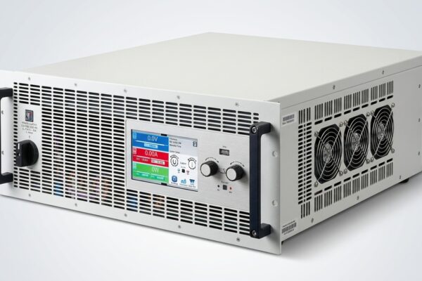
For laboratory validation and development work, TPS also supplies programmable bench power supplies, including the EA PS 3200 and EA PSI 9000 DT platforms.
For applications extending beyond standard cabinet power distribution, TPS also supports bidirectional AC/DC power solutions.
| GP compact DIN rail 10W-100W | Bench validation Programmable DC | |
| PRO DIN rail 24V / 30W-130W | Peak DR+ 100W-320W | Project-scale power Bidirectional modules |
RFQ checklist
Including the following information can help speed up technical evaluation:
- Required output voltage
- Continuous current
- Startup current
- Duration of peak loads
- Ambient cabinet temperature
- Available DIN rail space
- Mounting orientation
- Compliance requirements
- Expected order quantity
- Target delivery schedule
- Prototype or production requirements
- Requirement for equivalent solutions
Providing complete project information generally allows more accurate model recommendations and technical feedback.
Ready for quote-stage evaluation?
If your team is evaluating DIN rail power supplies for an upcoming project, provide the application requirements rather than only the target wattage. This helps ensure that the proposed model matches the intended operating conditions and project requirements.
FAQ
Is the 170% power boost intended for continuous operation?
No. According to the datasheet, the Peak DR+ Series provides a 170% power boost for up to 10 seconds with auto-recovery. It is intended to support short-duration overload events and should not replace correct continuous power sizing.
How should we choose between 12V and 24V versions?
Start with the actual downstream architecture. Choose the rail voltage that matches the controlled loads, wiring strategy, and installed equipment. Then size the PSU on continuous current, peak behavior, and cabinet conditions rather than nameplate wattage alone.
What compliance questions should be confirmed during the RFQ?
Confirm the exact customer or regional approval language required for the project. Even when the datasheet lists CE, EMC, and safety references, project acceptance may still depend on a customer-specific edition or documentation request.
Can TPS help identify equivalent solutions?
Yes. TPS can assist with model selection, discuss equivalent solutions where appropriate, and help evaluate suitable power supply options based on the application’s technical requirements.
When should the Peak DR+ Series be considered instead of a smaller DIN rail power supply?
The Peak DR+ Series may be appropriate for applications requiring higher output power or support for short-duration overload events. Comparing the application requirements with the GP and PRO Series can help identify the most suitable option.
Can the Peak DR+ Series replace an existing DIN rail power supply?
Replacement suitability depends on factors such as output voltage, current rating, available installation space, mounting requirements, and project-specific electrical or regulatory requirements. When replacing an existing unit, these parameters should be verified before selecting an equivalent model.