System integrators, test laboratory managers, and procurement teams rarely fail because they lack a specification for an electric vehicle component. They lose time—and budget—when the power supply infrastructure for a new battery or powertrain test facility cannot deliver the required voltage, current, and dynamic response. Or when it dissipates megawatts of energy as heat instead of recovering it. An EV battery pack undergoing a full charge‑discharge cycle at 800 V and 500 A dissipates 400 kW continuously. Without regenerative capability, the electricity cost and thermal management burden of this single test can dominate the facility’s operating budget.
TPS Elektronik’s EV test high power supply service addresses this challenge through a portfolio of programmable DC sources and regenerative power systems that scale from tens of kilowatts to multiple megawatts. By integrating advanced bidirectional power conversion, battery simulation software, and system‑level engineering, TPS delivers complete, turnkey power infrastructure for electric vehicle battery, powertrain, and component testing.
1. Why EV testing demands a new generation of high‑power supplies
The shift to 800 V vehicle architectures and the push for faster charging (350 kW and above) have rendered traditional unidirectional laboratory power supplies obsolete for many EV test applications. A battery cycler that can only charge a pack—but not discharge it—requires a separate resistive load bank to complete a full cycle. Which consuming energy and generating waste heat. A motor dynamometer test stand that cannot recover the mechanical energy from the motor under test loses it as heat, requiring enormous air‑conditioning capacity. The economic and environmental case for bidirectional, regenerative power systems is now overwhelming.
A programmable high power DC source with bidirectional capability solves this by integrating source and sink functions into a single instrument. Which recovering the absorbed energy to the AC grid with efficiencies exceeding 95 %. This not only reduces electricity costs but also simplifies the test setup—one instrument replaces two. The TPS approach to this grounded in extensive experience with custom power solutions, as demonstrated in our overview of custom power supply solutions and the case study on battery test systems.
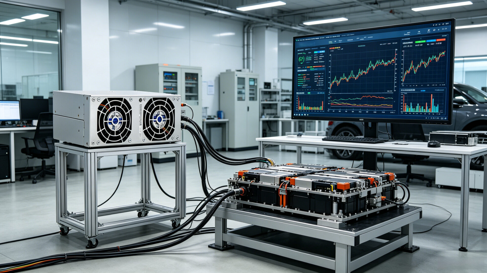
2. TPS EV test power supply solution overview
TPS Elektronik’s development service for EV test power supplies delivers complete, integrated systems rather than individual instruments. The scope includes specifying the appropriate power conversion hardware. Which designing the electrical distribution and safety systems, integrating the control software, and commissioning the completed test stand. This turnkey approach tailored to the specific test requirements. Whether it is a single‑channel battery cycler for a research laboratory or a multi‑megawatt, multi‑channel production test system.
2.1 Battery pack testing: charge/discharge cycling and simulation
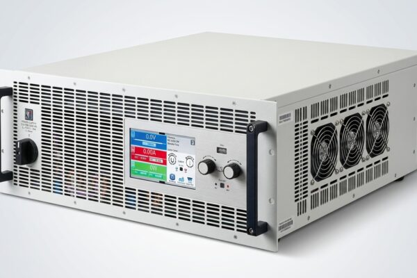
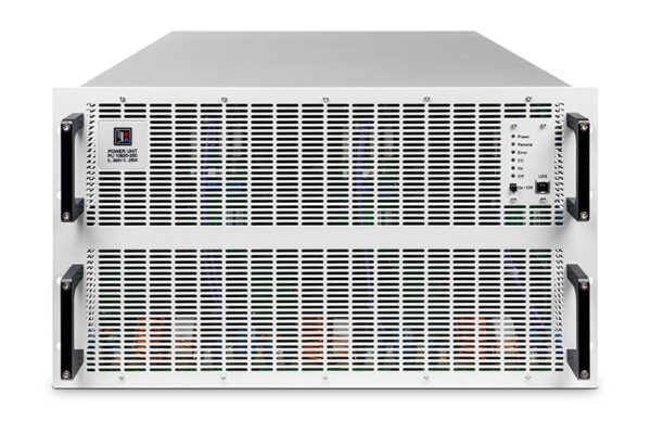
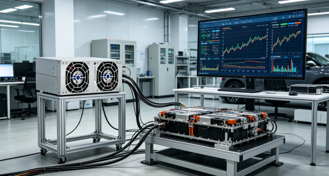
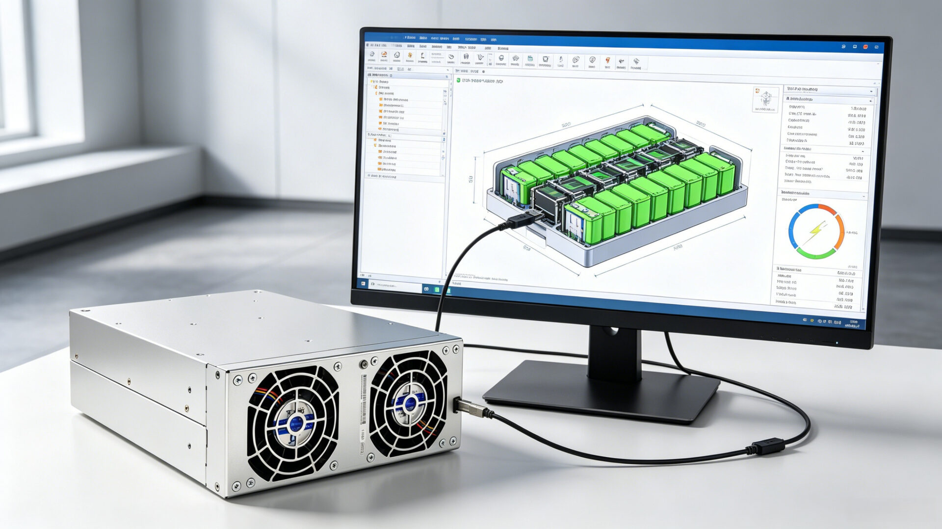
Battery testing requires a power supply that can emulate both the charging station (source mode) and the vehicle’s load (sink mode) with high dynamic response. TPS’s programmable DC sources, such as those based on the EA‑PU 10000 series and the TPS‑BM75053KTIF‑S bidirectional modules. Which can execute complex drive‑cycle profiles (e.g., WLTP, EPA UDDS) with sub‑millisecond response times. The integrated battery simulation software allows the power supply to emulate the electrical behavior of a specific battery chemistry. Which enabling hardware‑in‑the‑loop (HIL) testing of battery management systems (BMS) and on‑board chargers (OBC) without the need for a physical battery. For further background on custom battery test systems, refer to the detailed article on battery test system and custom power supply design.
2.2 Powertrain and inverter testing
Testing an electric motor and inverter requires a DC supply that can source current to the inverter during motoring operation and sink current from the inverter during regenerative braking. TPS’s high‑power bidirectional supplies provide this capability with seamless crossover between sourcing and sinking modes. The fast transient response ensures that the simulated DC‑link voltage remains stable even during rapid torque reversals. Which providing accurate and repeatable test conditions. This capability is a direct extension of the power electronics design expertise described in our guide on buck‑boost converter design and PCB layout reliability.
2.3 Regenerative energy recovery and grid integration
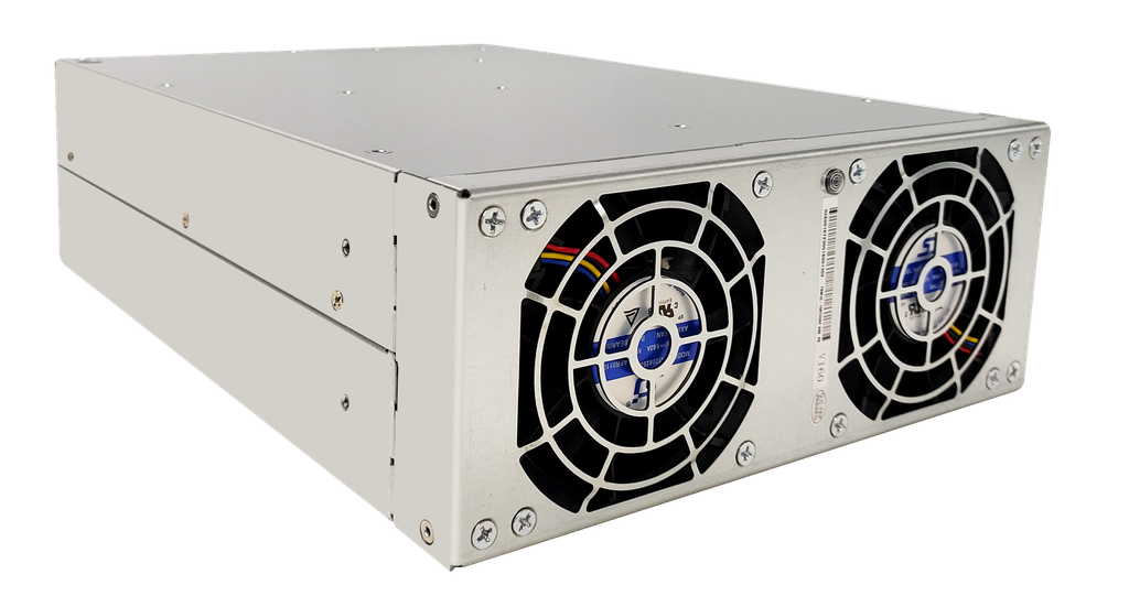
The regenerative capability of TPS’s bidirectional power supplies is a critical differentiator for high‑power test facilities. In battery cycling applications, the energy discharged from the battery converted back to AC and returned to the facility grid with up to 95 % efficiency, dramatically reducing net energy consumption. For a 1 MW battery test system operating continuously, this can represent annual electricity savings of several hundred thousand euros. The active power factor correction (typical PF >0.99) and low total harmonic distortion (THDi <5 %) ensure that the regenerated power meets grid‑code requirements without degrading the facility’s power quality.
3. System integration, scalability, and control
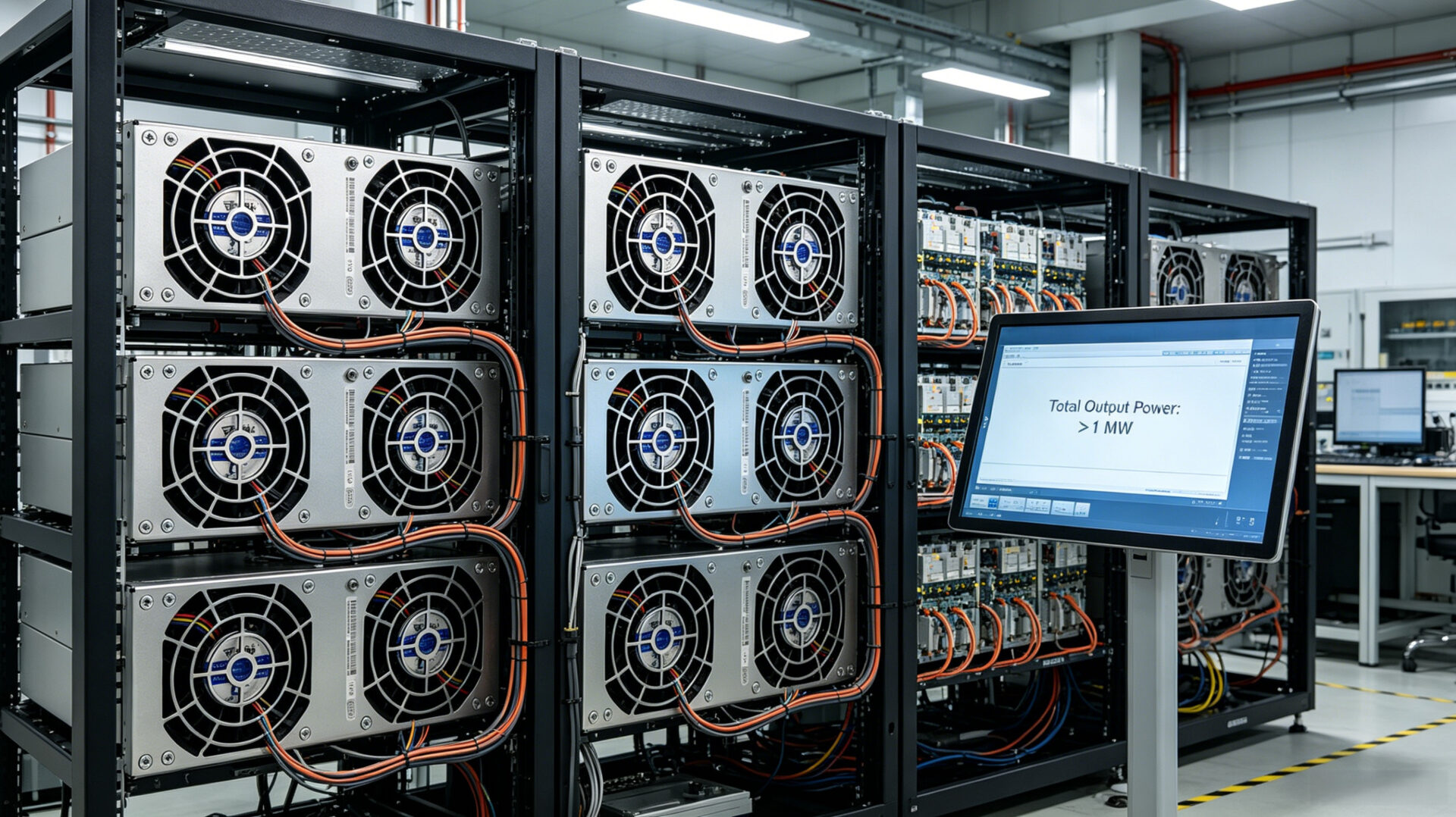
TPS’s development service extends beyond supplying power conversion hardware. For large‑scale test facilities, TPS engineers design and integrate the complete electrical infrastructure: AC distribution panels, DC busbar systems with low‑loss copper bars, safety interlocks, emergency stop circuits, and thermal management. The modular architecture of TPS power supplies allows them to be paralleled to scale power from tens of kilowatts to multiple megawatts (up to 64 units in parallel. Which delivering 3.84 MW from a single synchronized system). All systems are controlled through a unified software interface. Typically SCPI over Ethernet, with optional CAN, Profibus, or EtherCAT interfaces for integration into existing test automation platforms. This holistic integration approach is a core part of the broader development services for hardware, firmware, and protocol.
4. Safety, compliance, and automotive standards
High‑power EV test systems operate at hazardous voltage and current levels. TPS systems are designed to comply with the safety requirements of IEC 61010‑1 (safety requirements for electrical equipment for measurement, control, and laboratory use), as well as the relevant automotive standards: ISO 16750 for environmental conditions and electrical testing, and IEC 61851 for electric vehicle conductive charging systems. For facilities that require CE marking, TPS provides the necessary documentation, including a Declaration of Conformity, risk assessment, and test reports. The systems include comprehensive protection functions—overvoltage, overcurrent, overpower, and overtemperature—with adjustable thresholds and automatic shutdown sequences. Safety interlocks are integrated at both the hardware and software levels. Which ensuring that the system meets the rigorous safety expectations of automotive OEMs and test laboratories.
5. Application scenarios: battery, motor, OBC, and EMC testing
- Battery module and pack testing: Automated charge/discharge cycling for life‑cycle testing, performance characterization, and end‑of‑line production testing.
- Electric motor and inverter dynamometer testing: Providing a bidirectional DC link for motor test stands, with regenerative energy recovery to the grid.
- On‑board charger (OBC) testing: Simulating the AC grid on the input side and the battery on the output side. Which enabling complete OBC functional and efficiency testing.
- Automotive EMC testing: Supplying clean, high‑power DC to EV components inside an EMC chamber, where the power supply itself must be electromagnetically quiet and isolated from the measurement environment.
- DC fast‑charging station testing: Emulating an EV battery to test the output performance and communication protocols of DC fast chargers up to 350 kW.
6. RFQ checklist for EV test high power systems
- Test application: Battery cycling, powertrain, OBC, EMC, or other.
- Power requirements: Maximum DC voltage, maximum DC current, total power per channel, and number of channels.
- Bidirectional operation: Is regenerative energy recovery required?
- Dynamic performance: Required voltage and current slew rates, response time, and any specific drive‑cycle profiles.
- Control interface: Ethernet/SCPI, CAN, Profibus, EtherCAT, or other.
- Safety and compliance: Applicable standards (IEC 61010‑1, ISO 16750, IEC 61851), and required certifications (CE, UL, TUV).
- Facility integration: AC input voltage and capacity, cooling infrastructure, and any physical space constraints.
- Documentation: Required test reports, risk assessments, and certification support.
7. FAQ
What is the largest power system TPS can deliver for EV testing?
TPS can scale systems to multiple megawatts by paralleling power supply modules. A single synchronized system can reach 3.84 MW, and larger systems can be engineered by combining multiple subsystems.
Can TPS’s regenerative power supplies simulate a battery for HIL testing?
Yes. TPS provides battery simulation software that allows the power supply to emulate the electrical characteristics of a specific battery chemistry, enabling BMS and OBC testing without a physical battery.
What energy savings can be expected from a regenerative test system?
In battery cycling applications, over 95 % of the discharge energy is recovered to the grid, reducing net energy consumption by a similar percentage compared to a non‑regenerative system. The exact savings depend on the test profile and duty cycle.
Where can I learn more about TPS’s broader development and power supply capabilities?
Visit the TPS development service page, or explore our resources on custom power supplies and battery test systems.