System integrators, panel builders, and procurement teams rarely fail because they lack a power specification. They lose time — and budget. When the standard rack‑mount power shelves available from catalog distributors cannot meet the density, efficiency, or control requirements of next‑generation AI server racks. A 48 V shelf rated for 15 kW with basic analog control may work for a legacy compute cluster. It will not support a rack of eight GPU‑accelerated nodes demanding 30 kW with per‑module PMBus telemetry, dynamic phase shedding. And N+1 redundancy that must survive a single‑module failure without throttling the entire workload.
TPS Elektronik’s data center power supply design service addresses this gap by providing a fully custom, turnkey development process. From concept and schematic through PCB layout, thermal and EMC validation, prototyping, and series production. This service integrates seamlessly with TPS’s broader EMS capabilities, which including PCB assembly, cable harnessing, and system‑level box build, all under one quality management system.
1. Why custom power shelf design matters for AI and high‑density workloads
A standard 1U or 2U rack‑mount power shelf sourced from a broadline catalog offers a fixed output voltage, a predetermined number of slots, and limited or no digital communication. For a general‑purpose server rack, these constraints are acceptable. For an AI training cluster where each rack can draw over 40 kW and GPU power demands fluctuate dynamically during training runs, a catalog shelf becomes a performance bottleneck. It cannot dynamically adjust output voltage to optimize GPU power efficiency. It lacks the per‑module current monitoring necessary for predictive failure analysis. And it often fails to meet the tight rack‑level EMC requirements when dozens of shelves operate simultaneously.
Custom power shelf design solves these limitations by aligning the power architecture with the specific electrical and mechanical requirements of the rack and the workload. TPS develops shelves that integrate CRPS (Common Redundant Power Supply) modules. A form factor standardized by OCP and widely adopted for high‑density data centers — into a mechanical frame with integrated backplane, busbar distribution, and optional battery backup interfaces. This results in a power system that fits precisely within the target rack depth. Which delivers the exact output voltage and power rating required, and communicates real‑time telemetry to the rack management controller. For a broader overview of how custom power solutions are developed at TPS, see the dedicated custom power supply page.
2. TPS power supply design capability overview
TPS Elektronik’s development service for data center power supplies covers the complete engineering cycle. The service starts with a detailed requirement specification and proceeds through system architecture, component selection, schematic design, PCB layout, mechanical enclosure and busbar design, prototype build, and comprehensive validation testing. Once the design is proven, TPS can transition the product into series manufacturing within its EMS facilities. Which providing a single accountable partner from concept to volume shipment.
2.1 Custom power shelf design: mechanical and electrical integration
The power shelf is both an electrical and a mechanical system. Electrically, it must combine the outputs of multiple power modules into a single high‑current bus with minimal voltage drop and parasitic inductance. Mechanically, it must fit within the constrained 1U or 2U height of a standard 19‑inch rack, accommodate the depth restrictions of the cabinet, and provide front‑to‑rear or side‑to‑side airflow that aligns with the rack’s cooling strategy.
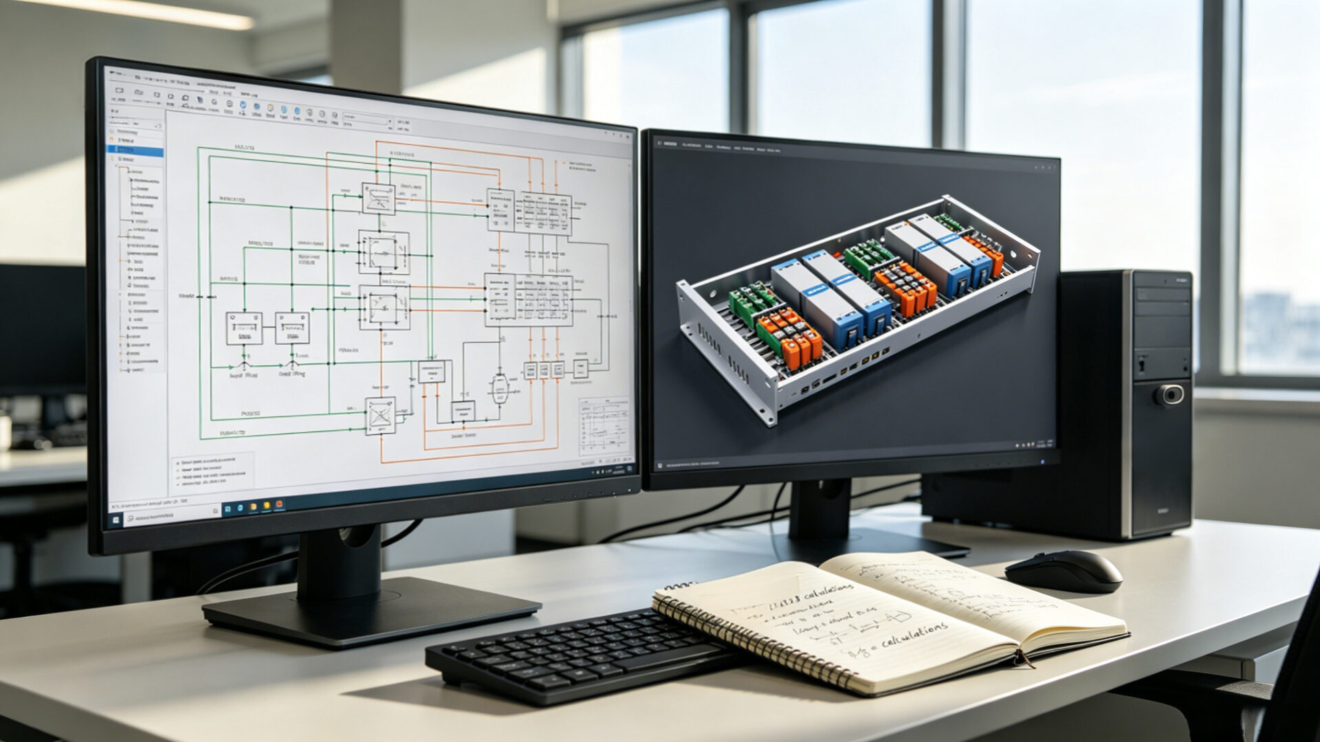
TPS addresses these requirements through an integrated ECAD‑MCAD design process. The electrical team designs the backplane or busbar distribution, OR‑ing circuits, input filtering, and protection. While the mechanical team simultaneously designs the sheet‑metal enclosure, module guide rails, and connector alignment. This concurrent engineering approach ensures that the final assembly meets electrical performance targets (efficiency, ripple, transient response) without mechanical interference or thermal hot spots. For more on how this design process supports complex systems, see the case study on custom power supply design and battery test systems.
2.2 CRPS module integration and busbar architecture
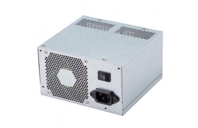
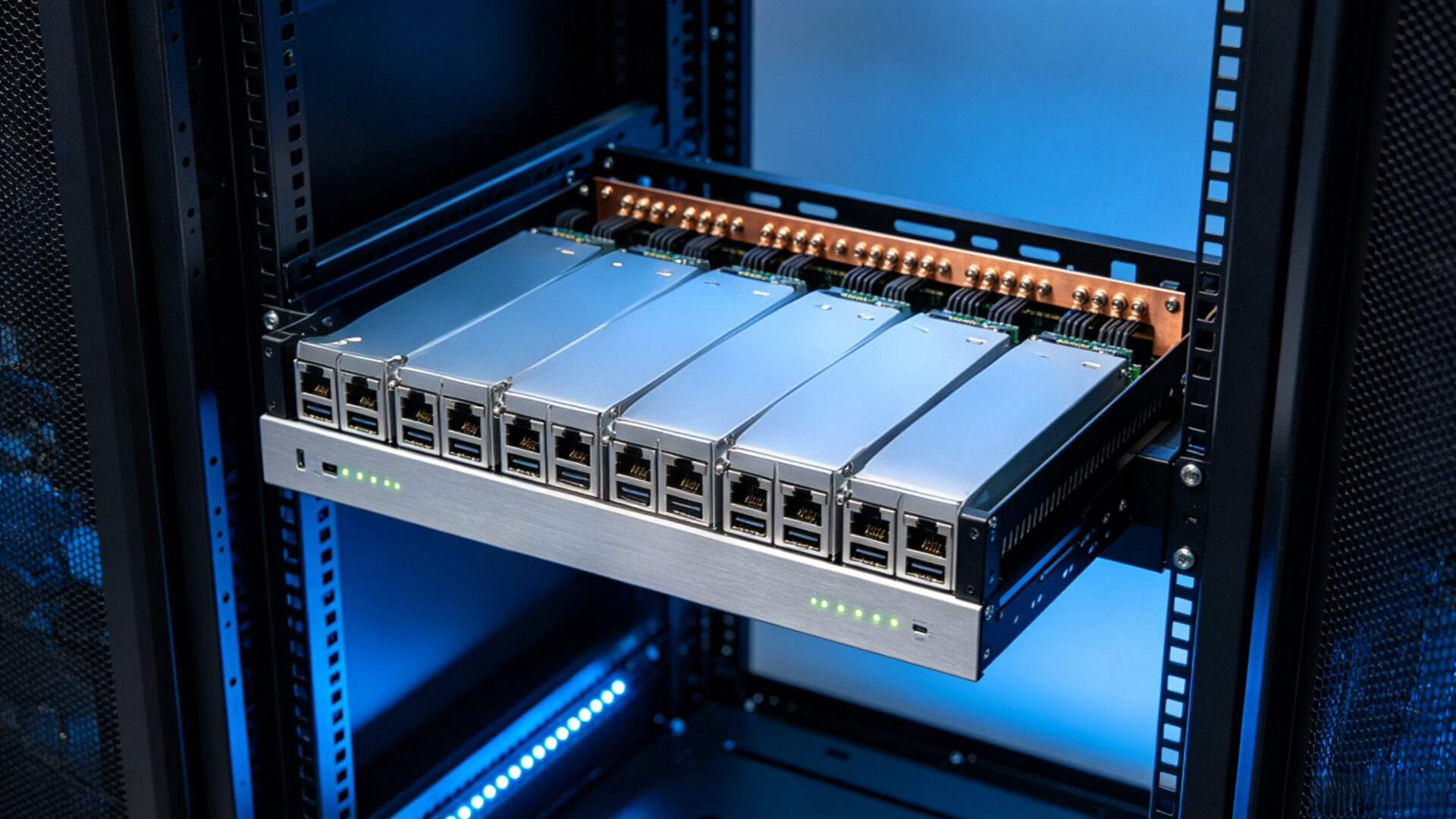
CRPS modules provide a standardized power supply form factor (185 mm × 73.5 mm × 40 mm for the common 1U format) with output power ratings typically ranging from 1.6 kW to 3.2 kW per module. By combining multiple CRPS modules on a single power shelf, the total rack power can scale from a few kilowatts to over 30 kW. TPS designs the backplane and busbar system that interconnects these modules. Which ensuring that current sharing is balanced, that hot‑swap insertion and extraction do not disrupt the output bus. And that a single module failure is isolated without affecting the remaining modules.
The busbar design is a critical element. At 48 V and 600 A, a 1 mΩ resistance in a busbar connection dissipates 360 W as heat — unacceptable in a dense rack environment. TPS designs busbars using copper bar stock with silver or tin plating, sized to limit voltage drop and temperature rise. Insulation coordination and creepage distances are verified against IEC 62368‑1 requirements. And partial discharge testing is conducted where required for high‑voltage isolation. For further technical detail on power electronics design, refer to the article on buck‑boost converter design and PCB layout reliability.
3. Thermal management and efficiency optimization
Efficiency is not an abstract metric in a data center — it directly determines operating cost and cooling infrastructure requirements. A power shelf that operates at 94 % efficiency dissipates 6 % of its rated output as heat. At 30 kW output, that is 1.9 kW of heat that the rack’s cooling system must remove. Improving efficiency to 96 % reduces heat dissipation to 1.25 kW — a 34 % reduction that compounds across hundreds of racks.
TPS optimizes power shelf efficiency through multiple design choices. The power topology is selected to minimize switching and conduction losses: interleaved boost PFC for the AC input stage, phase‑shifted full‑bridge or LLC resonant converters for the DC/DC stage, and synchronous rectification using low‑Rds(on) MOSFETs for the output. Component selection prioritizes GaN FETs or SiC diodes where the efficiency gain justifies the cost premium. Thermal simulation validates that hot‑spot temperatures remain within component ratings under worst‑case ambient conditions (typically 40 °C inlet air). For additional context on how thermal design integrates with broader system development, see the overview of development services for hardware, firmware, and protocol.
4. Control, monitoring, and redundancy
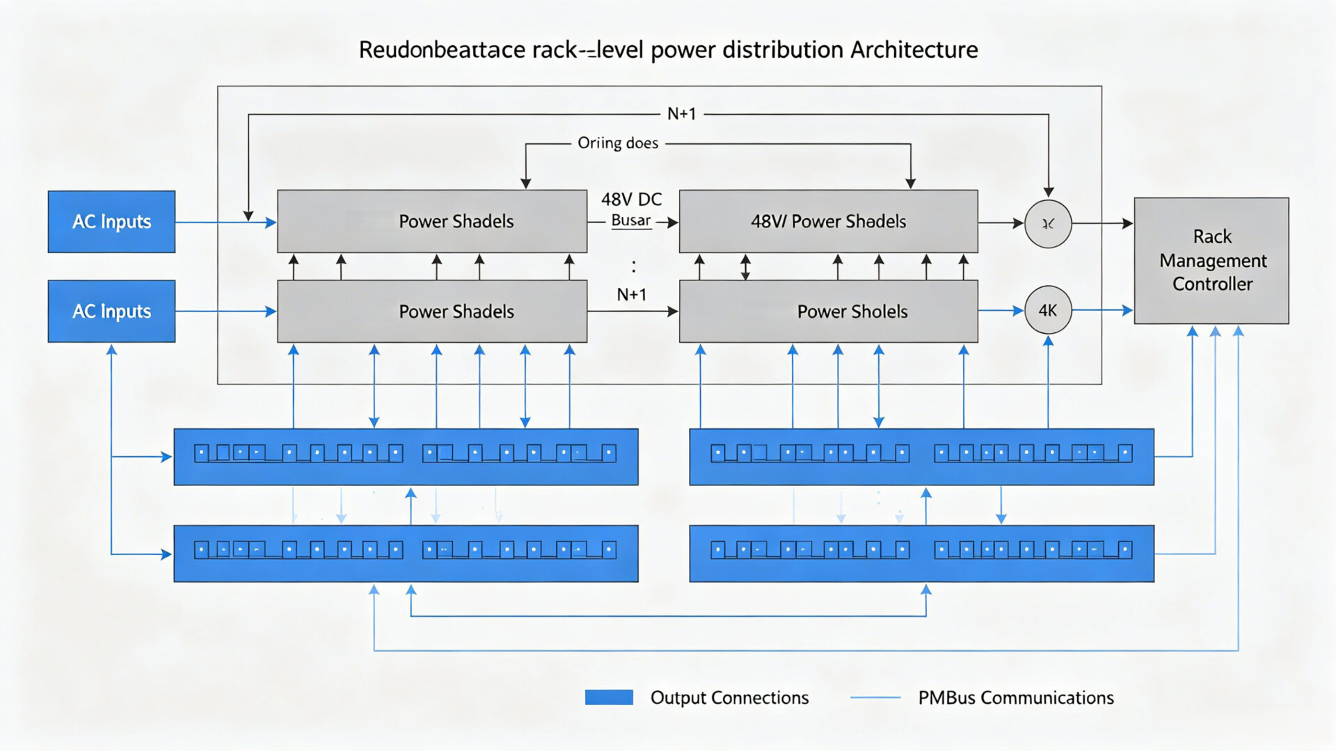
Modern data center power shelves are not just power converters; they are managed subsystems within the rack’s digital infrastructure. TPS integrates digital control and monitoring capabilities into every custom power shelf design. PMBus communication on each CRPS module enables real‑time reporting of input and output voltage, current, power, temperature, fan speed, and fault status. The shelf controller aggregates this data and presents it to the rack management controller via a standard interface (typically I²C or Ethernet).
Redundancy is a fundamental requirement. TPS designs shelves that support N+1 or 2N redundant module configurations. Active OR‑ing circuits using low‑loss MOSFETs ensure that a short‑circuit failure on one module does not pull down the shared output bus. Hot‑swap controllers limit inrush current during module insertion, preventing bus voltage disturbance. These features are validated during prototype testing under both steady‑state and dynamic load conditions. A relevant case study on how custom power design supports reliable test systems is available in the article on battery test system and custom power supply design.
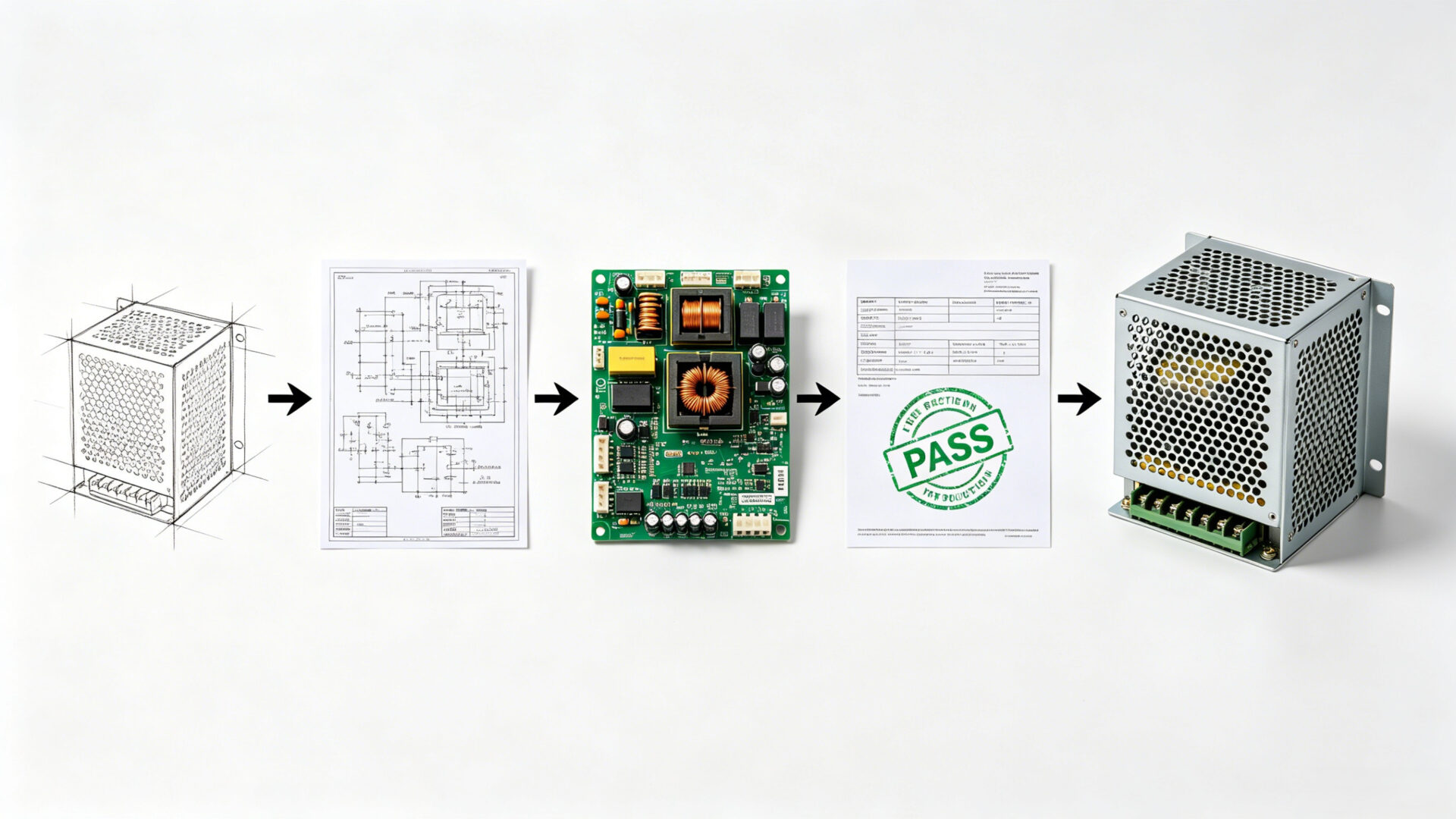
5. Development process: from specification to production
TPS follows a structured development process for custom power supply projects, designed to identify and resolve risks at the earliest possible stage. The process includes:
- Requirement analysis: TPS engineers work with the customer to define electrical specifications (input voltage range, output voltage and current, efficiency, hold‑up time), mechanical constraints (form factor, depth, connector locations), control interfaces (PMBus, analog, discrete signals), and applicable standards (IEC 62368‑1, CISPR 32, EN 55032).
- System architecture and component selection: Topology selection, key component identification (power semiconductors, magnetics, capacitors), and block diagram development.
- Schematic and PCB layout: Detailed design captured in ECAD, with DFM review and thermal simulation. For complex boards, TPS leverages the same PCB design capabilities described in the medical device PCB design services and circuit breaker panel design resources.
- Mechanical design: Enclosure and busbar design in MCAD, integrated with the electrical layout to ensure connector alignment and thermal interface integrity.
- Prototype build and test: Assembly of initial units, followed by functional testing, efficiency measurement, thermal validation in a controlled chamber, EMC pre‑compliance testing, and safety verification.
- Production transition: Once the design is validated, TPS can manufacture the power shelf in series, leveraging its EMS capabilities for PCB assembly, cable harnesses, and system integration. This full lifecycle approach is further detailed in the guide on development services for hardware, firmware, and protocol.
6. Certifications and compliance for data center power systems
Compliance is not an afterthought in TPS development projects. The design process incorporates the relevant standards from day one. For data center power shelves destined for the European market, the applicable directives include the Low Voltage Directive (2014/35/EU) and the EMC Directive (2014/30/EU). The primary safety standard is IEC 62368‑1, the hazard‑based safety standard for audio/video, information, and communication technology equipment. EMC compliance is demonstrated against CISPR 32 / EN 55032 for emissions and IEC 61000‑4‑x for immunity.
TPS provides full documentation to support the customer’s CE marking or other regulatory submissions, including design calculations, test reports, and a declaration of conformity. For North American markets, TPS can design to meet UL 62368‑1 and the relevant NRTL requirements, supporting certification by a Nationally Recognized Testing Laboratory.
7. RFQ checklist for custom power supply design
- Electrical specification: Input voltage range (AC or DC), output voltage and current, total output power, hold‑up time, efficiency targets.
- Form factor and mechanical constraints: Rack unit height (1U, 2U), maximum depth, connector type and location, airflow direction.
- Redundancy and hot‑swap: N+1 or 2N, hot‑swap insertion/removal, OR‑ing circuit requirements.
- Control and monitoring: PMBus, analog control, discrete status signals, communication interface to rack management controller.
- Applicable standards: Safety (IEC 62368‑1, UL 62368‑1), EMC (CISPR 32, EN 55032), environmental (operating temperature, altitude).
- Volume and timeline: Prototype quantity, pilot run volume, series production volume, target delivery dates.
- Documentation: Design files, test reports, compliance certificates, user manual.
8. FAQ
What is the typical development timeline for a custom power shelf?
A typical project from specification to prototype delivery ranges from 12 to 20 weeks, depending on complexity. Factors include power level, control interface complexity, and the extent of compliance testing required. TPS provides a detailed project schedule during the quotation phase.
Can TPS design to meet OCP Open Rack specifications?
Yes. TPS can design power shelves that comply with OCP mechanical and electrical specifications, including CRPS module interfaces and 48 V bus distribution. Specific OCP version requirements should be stated during the RFQ process.
Does TPS provide firmware development for digital power control?
Yes. TPS develops embedded firmware for digital power controllers, including PMBus communication stacks, protection algorithms, and efficiency optimization routines. The firmware is developed alongside the hardware, with testing on real prototypes. See the development services page for details.
Is thermal simulation included in the design service?
Thermal simulation is a standard part of the design process. TPS uses computational fluid dynamics (CFD) tools to model airflow and temperature distribution, and validates the simulation with physical testing in a thermal chamber.
Where can I learn more about TPS development capabilities?
Visit the TPS development service page, or explore related case studies on custom power supply design and battery test system power design.


