For system integrators, electrical engineers, and procurement teams developing wearable electronics, the gap between a working design and a manufacturable product often bridged by prototyping. Wearable devices—smartwatches, fitness trackers, medical sensors, and hearables—demand flexible and rigid-flex PCB architectures that can survive bending, twisting, and continuous wear. Validating these designs requires prototyping services that understand not only PCB assembly but also the unique mechanical and environmental stresses of wearable applications.
TPS Elektronik’s electronics prototyping services combine flexible and rigid-flex PCB fabrication, precision SMT assembly, and comprehensive validation testing to help engineering teams move from concept to production-ready wearable designs. From DFM review and material selection through prototype builds and functional testing, TPS supports the entire NPI journey—so that when you commit to production tooling, your design is already proven.
1. Why Wearable Electronics Demand Flexible and Rigid-Flex Prototyping
Wearable electronics are not simply smaller versions of conventional PCBs. They are mechanical systems that must survive the human body in motion. A smartwatch flexes slightly with every wrist movement. A fitness tracker bends during exercise. A medical patch conforms to skin while monitoring vital signs. These applications demand PCB architectures that combine electrical performance with mechanical flexibility and long-term reliability.
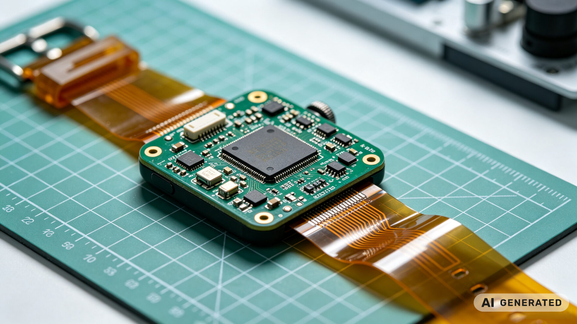
Flexible PCBs use polyimide or other flexible substrates to create circuits that can bend and fold. They are ideal for space-constrained designs where a rigid board cannot fit, or where dynamic bending required. Rigid-flex PCBs combine rigid sections for components and connectors with flexible sections for interconnects, allowing a single assembly to span multiple planes within a wearable enclosure.
For engineering teams, validating these designs through prototyping is essential because:
- Mechanical stress is difficult to simulate: Bending, twisting, and flexing create stresses that are hard to model accurately without physical testing.
- Assembly processes differ: Flexible and rigid-flex boards require different handling, stiffeners, and reflow profiles than standard FR-4.
- Reliability requirements are strict: Wearables are worn daily and must survive sweat, temperature changes, and repeated motion.
- Form factor is critical: Every millimeter counts, and the prototype must fit the enclosure and the human body.
TPS Elektronik’s prototyping services designed for exactly these challenges. By combining PCB fabrication, assembly, and test under one roof, TPS helps teams iterate quickly and catch design issues before they become production problems. For a broader overview of TPS capabilities, see the Electronic Manufacturing Services Complete Guide.
2. The TPS Electronics Prototyping Services Approach
TPS Elektronik approaches prototyping as a validation process, not just a manufacturing step. The goal is to provide engineering teams with functional prototypes that can be tested, measured, and refined—so that the final design is robust and production-ready.
Design for Manufacturing (DFM) Review: Before fabrication begins, TPS engineers review the design for manufacturability. For flexible and rigid-flex boards, this includes checking bend radii, stiffener placement, coverlay openings, and trace routing across flex zones. DFM feedback at this stage prevents costly redesigns later.
Material Selection: Flexible PCBs can use polyimide, polyester, or other substrates. Adhesiveless laminates preferred for dynamic flexing. Rigid-flex boards combine FR-4 rigid sections with polyimide flex layers. TPS helps teams select materials based on bend requirements, temperature range, and cost. For more on materials, see the Electronic Components & PCB Guide.
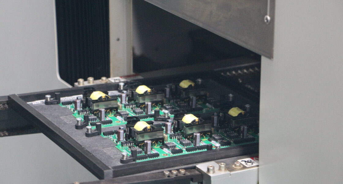
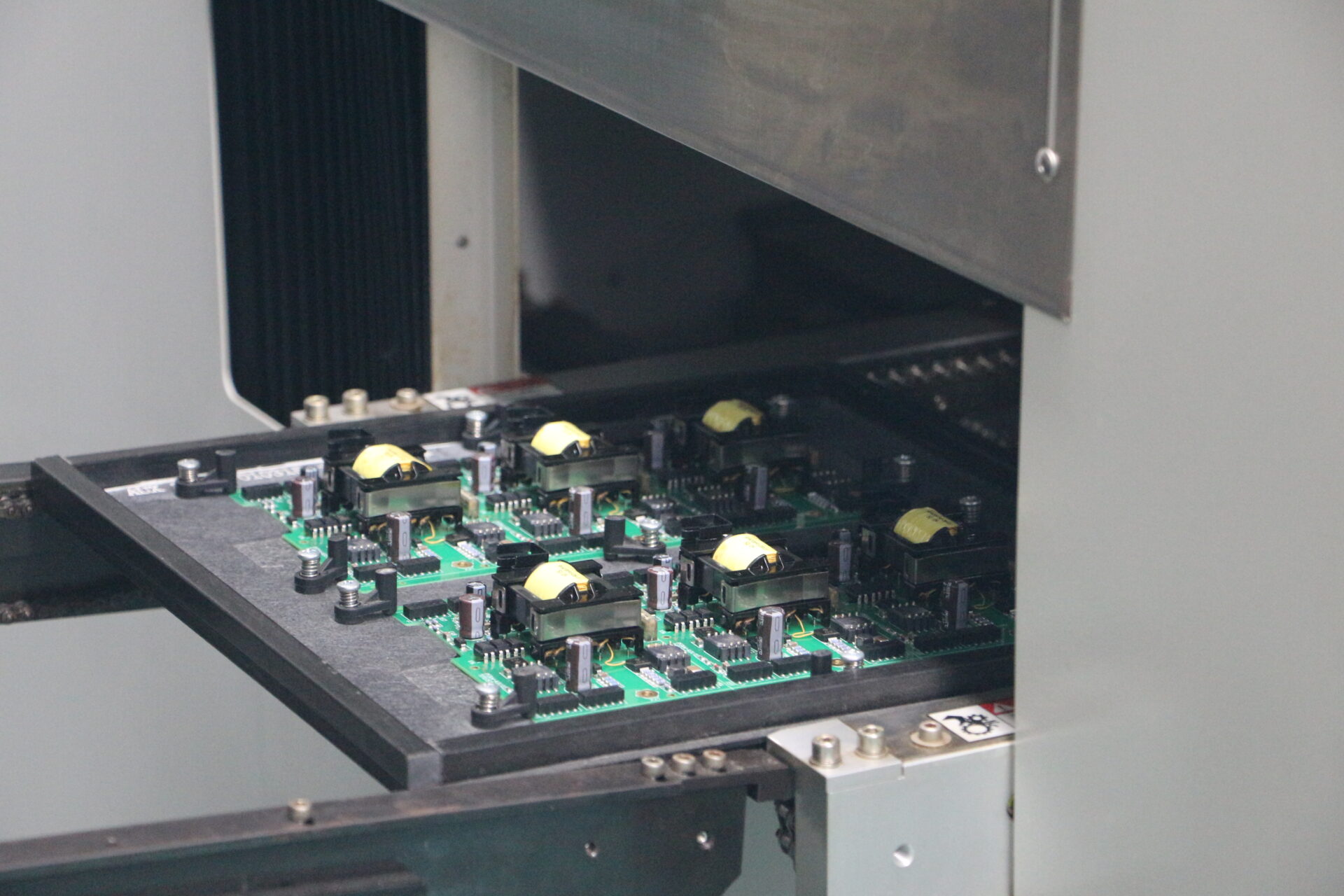
Prototype Fabrication and Assembly: TPS fabricates flexible and rigid-flex prototypes with controlled impedance, fine-pitch traces, and appropriate surface finishes. Assembly performed on SMT lines capable of handling thin, flexible substrates with carriers and fixtures that prevent damage during reflow. For complex mixed-technology assemblies, TPS also provides SMD and THT assembly.
Testing and Validation: Every prototype build includes electrical test, visual inspection, and functional verification. For wearables, TPS can also support mechanical flex testing, environmental exposure, and reliability screening.
By providing a single source for fabrication, assembly, and test, TPS reduces the coordination burden on engineering teams and accelerates the iteration cycle. Learn more about the full service range at PCB Assembly Services EMS Guide.
3. Flexible PCB Prototyping: Materials, Stackups, and Design Rules
Flexible PCB prototyping requires careful attention to materials, stackups, and design rules that differ significantly from rigid boards. TPS Elektronik’s prototyping services address these factors to ensure that flexible circuits perform reliably in wearable applications.
Base Materials: Polyimide (PI) is the most common substrate for flexible PCBs due to its high temperature resistance, mechanical strength, and dielectric properties. Adhesiveless laminates are preferred for dynamic flexing because they eliminate the adhesive layer that can crack under repeated bending. For less demanding applications, polyester (PET) may be used for cost-sensitive designs.
Copper Thickness: Thinner copper (e.g., 1/2 oz or 1 oz) is more flexible than heavy copper. For dynamic flexing, rolled annealed (RA) copper is preferred over electrodeposited (ED) copper because it has better ductility and fatigue resistance.
Coverlay and Stiffeners: Coverlay (cover layer) protects the copper traces and provides insulation. It must properly opened at bend areas to allow flexing without cracking. Stiffeners (FR-4, polyimide, or stainless steel) added to rigid sections or connector areas to provide mechanical support.
Design Rules for Flex: Bend radius should be at least 10 times the total thickness for dynamic flexing and 5 times for static flexing. Traces should run perpendicular to the bend line where possible. Plated through-holes should be avoided in bend areas. TPS provides detailed DFM feedback to ensure these rules applied.
For wearable devices, flexible PCBs enable designs that conform to the body, fit into tight enclosures, and survive repeated motion. TPS prototypes these designs with the precision needed to validate performance before production. For medical wearable applications, see EMS PCB Assembly Rapid Prototyping for Medical.
4. Rigid-Flex Prototype Assembly: Challenges and Solutions
Rigid-flex PCBs combine the best of both worlds: rigid sections for component mounting and connectors, and flexible sections for interconnects. However, assembling rigid-flex prototypes presents unique challenges that TPS Elektronik is equipped to handle.
Handling and Fixturing: Rigid-flex boards are thin and flexible in the flex areas, making them difficult to handle in standard SMT equipment. TPS uses dedicated carriers and fixtures that support the board during printing, placement, and reflow. This prevents warping, misalignment, and damage to the flex sections.
Reflow Profiling: The thermal mass of rigid-flex boards varies between rigid and flex areas, requiring carefully developed reflow profiles. TPS uses thermal coupons and profiling to ensure that all areas of the board reach the correct temperatures without overheating the flex sections.
Component Placement: Fine-pitch components, including BGA and QFN packages, can placed on rigid sections with high accuracy. TPS’s SMT lines are capable of handling these components, and the company’s experience with PCB assembly ensures reliable solder joints.
Stiffener Attachment: Stiffeners often attached to rigid-flex boards to provide mechanical support at connectors or component areas. TPS applies stiffeners with precise alignment and appropriate adhesives to ensure reliability.
By addressing these challenges, TPS delivers rigid-flex prototypes that are functional, testable, and representative of the final production assembly. This allows engineering teams to validate the design under realistic conditions.
5. Validation and Test: Ensuring Wearable Reliability
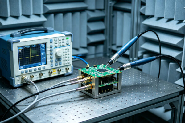
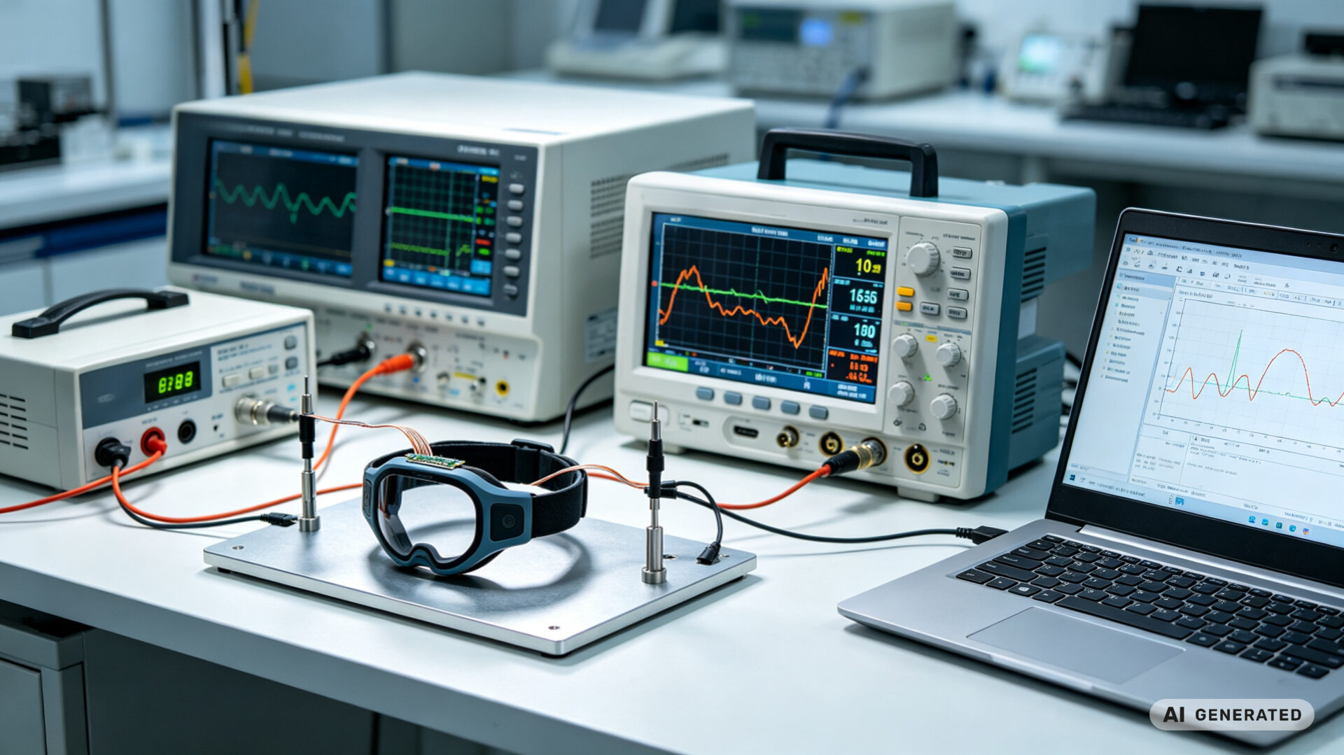
Prototyping is not complete without validation. For wearable electronics, validation must go beyond basic continuity and functional tests. The device must survive the mechanical and environmental stresses of daily wear. TPS Elektronik’s prototyping services include a range of validation tests to ensure reliability.
Electrical Test: Every prototype undergoes 100% continuity and isolation testing. For high-speed signals, impedance and insertion loss can verified. Functional test can be performed with custom fixtures or customer-provided test equipment.
Mechanical Flex Testing: Flexible and rigid-flex prototypes can be subjected to dynamic bending tests to simulate wrist movement, folding, or twisting. TPS can perform bend testing at specified radii and cycle counts, monitoring for electrical opens or impedance changes.
Environmental Testing: Wearables must survive sweat, humidity, and temperature variation. TPS can support environmental exposure testing, including temperature cycling and humidity soak, to validate material and assembly reliability.
Reliability Screening: For critical applications, TPS can perform additional screening such as thermal shock, vibration, and ionic cleanliness testing. These tests help identify potential failure modes before production.
By validating prototypes under realistic conditions, TPS helps engineering teams avoid field failures and warranty costs. The data from these tests also supports regulatory submissions and customer qualification. Learn more about TPS test capabilities at Electronic Manufacturing Services Complete Guide.
6. From Prototype to Production: NPI Support
Once a wearable design has been validated through prototyping, the next step is new product introduction (NPI). TPS Elektronik supports the transition from prototype to production with a structured NPI process that ensures design intent is preserved and manufacturing is repeatable.
Design Transfer: TPS works with the customer to transfer the validated design into production documentation. This includes Gerber files, assembly drawings, BOMs, and test specifications. Any changes identified during prototyping are incorporated.
Process Qualification: The production process qualified with pilot builds. For flexible and rigid-flex boards, this includes verifying fabrication tolerances, assembly parameters, and test coverage. First Article Inspection (FAI) reports document the results.
Supply Chain Setup: TPS manages component sourcing, including long-lead items and specialized materials. The company’s supply chain team ensures that production materials meet the same specifications as those used in prototyping.
Production Ramp: TPS scales production from pilot to volume, maintaining the same quality management system (ISO 9001, ISO 13485 for medical, IATF 16949 for automotive) throughout. For medical wearables, TPS follows ISO 13485 requirements, as described in EMS PCB Assembly Rapid Prototyping for Medical.
By providing a seamless path from prototype to production, TPS reduces risk and time-to-market for wearable electronics. Engineering teams can focus on innovation, knowing that manufacturing is in capable hands.