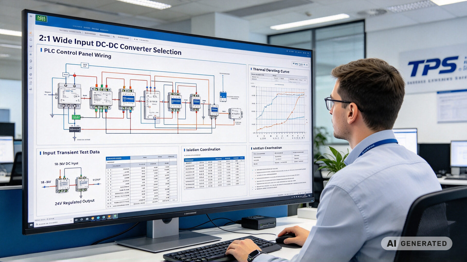


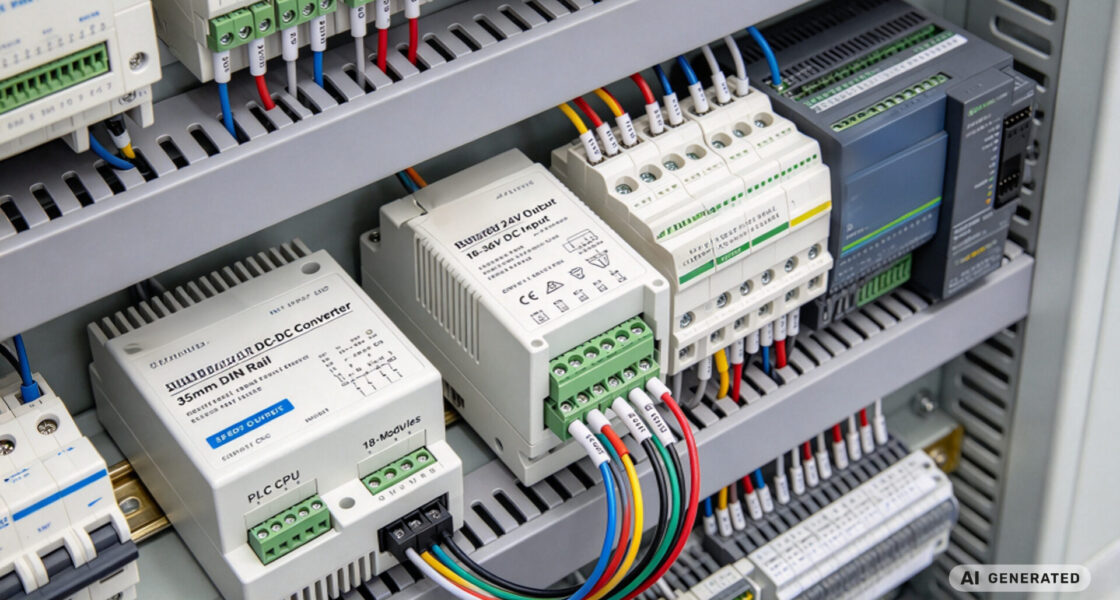
System integrators, panel builders, and procurement teams in factory automation rarely lose production time because the PLC logic is wrong. They lose it when the 24V control bus dips below the PLC’s input tolerance during a motor start, when a contactor drop-out resets an I/O rack, or when a long cable run introduces enough voltage drop that the control power supply leaves regulation.
TPS Elektronik’s mechatronics integration services are built to reduce that risk: 2:1 wide input DC-DC converter selection, PLC control panel integration, thermal and transient validation, and documented power architecture from prototype through series production.
1. What a 2:1 wide input DC-DC converter does for a 24V bus
A 2:1 wide input DC converter accepts an input voltage range where the maximum input is twice the minimum—for example 9–18V, 18–36V, or 36–72V. For a nominal 24V factory automation bus, the relevant range is typically 18–36V. Within that range, the converter maintains a regulated isolated output—often 24V, 12V, or 5V—for PLC CPUs, I/O modules, sensors, HMIs, and communication gateways.
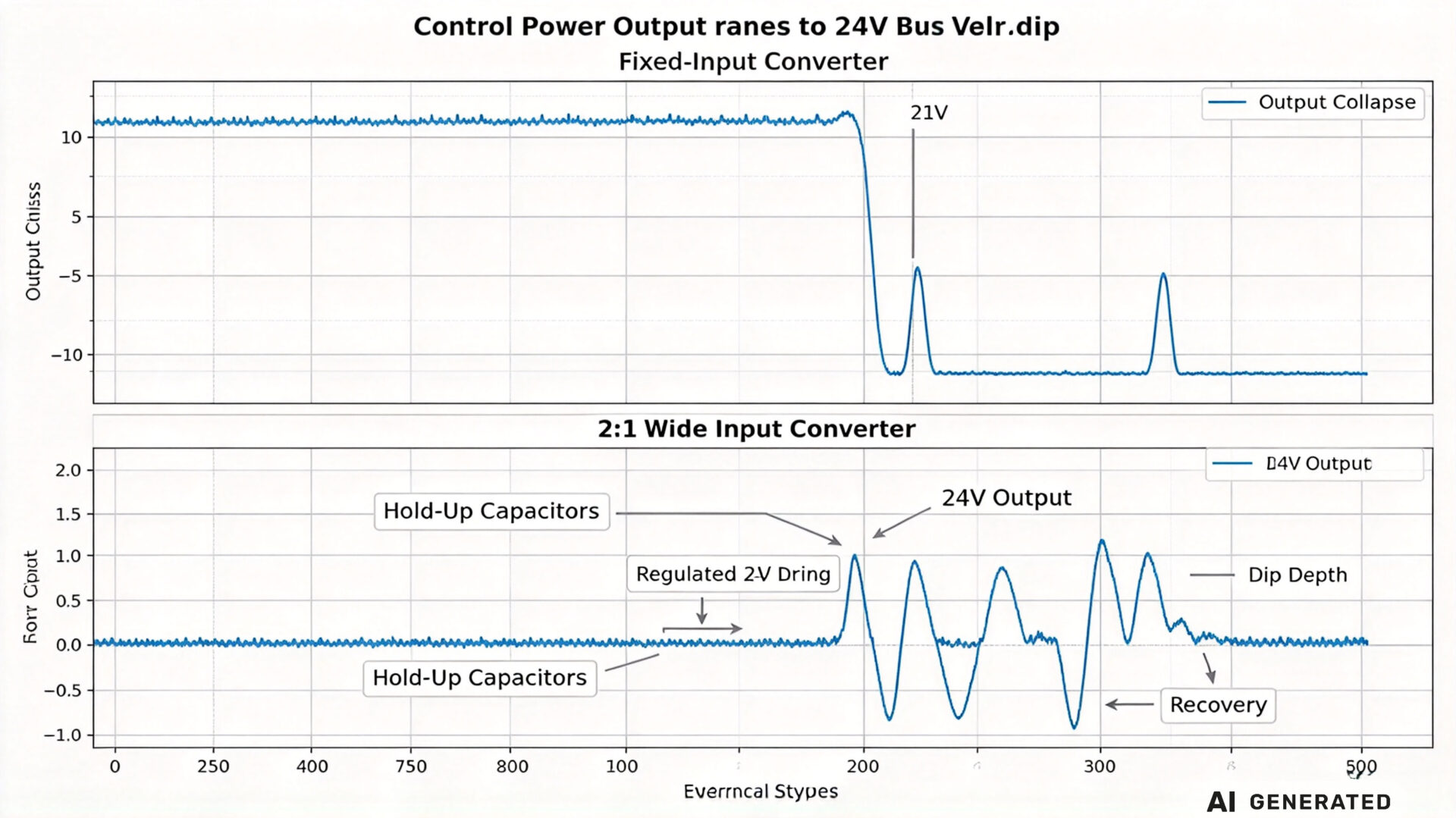
The difference between a 2:1 converter and a fixed-input converter is not a marketing detail. It is the difference between a control power supply that rides through a bus dip and one that drops out, resets the PLC, and forces a line restart. IEC 61131-2 defines the electrical service conditions and ride-through requirements for programmable controllers, but the converter feeding the PLC must itself remain in regulation for the PLC to meet those requirements.
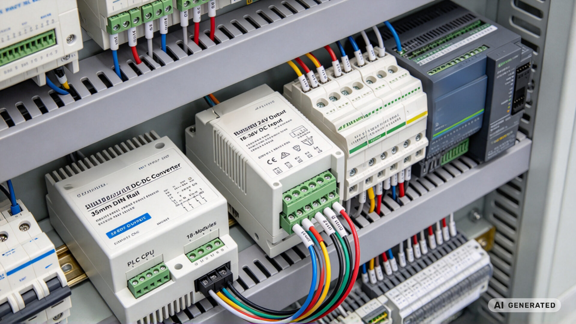
1.1 Where 24V bus fluctuations come from
In a real factory cabinet, the 24V bus is never a clean laboratory source. The dominant fluctuation sources are:
- Motor and drive starts: A 24V bus shared with contactor coils, brake rectifiers, or small drives experiences dips when inductive loads energize.
- Contactor drop-out and regeneration: When a contactor opens, stored magnetic energy can produce a transient rise on the bus.
- Long cable runs: Voltage drop along 24V distribution cables means the converter at the end of the run sees a lower voltage than the power supply output.
- Battery-backed or UPS-backed sections: During a mains failure, the 24V bus may fall as the battery discharges, even while the PLC is expected to complete a controlled shutdown.
- Multiple power supply sharing: Paralleled or diode-coupled 24V supplies can exhibit unequal loading and transient mismatch.
These events are not rare. They occur every shift, and their depth depends on cable length, load profile, and the impedance of the 24V distribution system. A converter specified only for 24V nominal ±10% (21.6–26.4V) leaves no margin for a 17.5V motor-start dip.
1.2 Why fixed-input converters fail in real cabinets
A fixed-input converter with a narrow input window may work on the bench and fail in the cabinet. The failure mode is not always a hard shutdown. More often, the converter enters undervoltage lockout (UVLO), the output drops, the PLC resets, and the machine returns to its home position—producing a scrap part and an operator intervention. In safety-related control circuits, the consequence can be more serious.
The procurement consequence is equally clear: a low-cost narrow-input converter that causes one unplanned line stop per month costs more than a 2:1 wide input converter that prevents it. For panel builders, the wide-input converter also simplifies stock: one part number can cover 24V systems with different cable lengths and load profiles.
2. Design checklist for stable control power
Selecting a 2:1 wide input converter is necessary but not sufficient. Stable control power requires the converter, the input filter, the hold-up capacitance, the output distribution, and the panel grounding to be designed as one system.
2.1 Input range, UVLO, and low-line efficiency
The first check is the input range against the measured bus behaviour, not the nominal voltage. If the bus dips to 17.5V during motor starts, an 18–36V converter is already at its lower limit. In that case, either the bus distribution must be improved, or a converter with a lower minimum input—such as a 9–36V or 4:1 range—should be selected.
UVLO threshold and hysteresis matter as much as the range. A UVLO that engages at 17.0V and releases at 17.5V will cause chatter if the bus hovers near the threshold. Specify UVLO with adequate hysteresis, and verify the low-line efficiency: a converter that is 90% efficient at 24V may be only 82% efficient at 18V, which increases internal heat exactly when the cabinet is already stressed.
2.2 Hold-up, transient response, and output regulation
Hold-up time is the time the output remains in regulation after the input falls below the UVLO threshold. For a PLC that must complete a controlled shutdown, hold-up must cover the shutdown sequence—typically 10–50ms depending on the PLC and the application. Hold-up is provided by input capacitance, not by the converter alone; the converter datasheet hold-up value is measured at a specific load and input voltage and must be recalculated for the actual load.
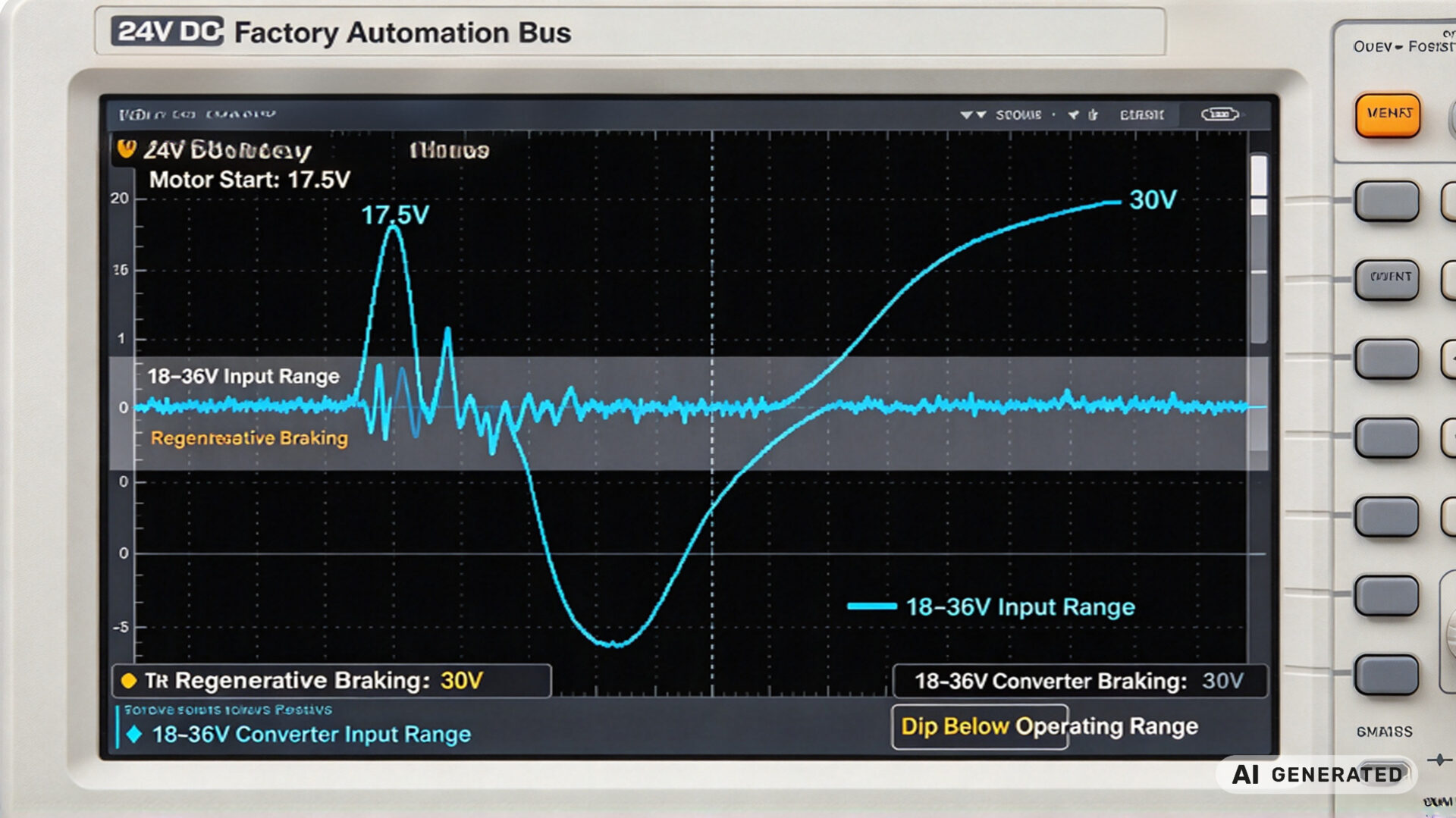
Transient response determines how far the output deviates when the load steps—for example when a bank of relays energizes. A converter with fast transient response and low output impedance keeps the PLC input voltage within tolerance. Output ripple must also be checked at the actual switching frequency and load, not only at nominal conditions.
2.3 Isolation, safety, and EMC coordination
Isolated converters are standard in factory automation because they break ground loops between the 24V distribution system and the control electronics, and because they provide a defined isolation barrier for SELV circuits. The isolation voltage, creepage and clearance distances, and the applicable safety standard must be verified against the panel’s safety concept. IEC 61558-1 and the relevant part 2 standards define transformer and insulation requirements for small power supplies.
EMC coordination is the second half of the isolation story. A wide input converter switches at high frequency; without adequate input filtering, it can conduct noise onto the 24V bus and radiate from the input cables. The converter should be specified with conducted emissions compliant to CISPR 11 / EN 55011 Class A or B as required by the installation environment, and the panel layout should keep input and output cables separated.
3. How TPS integrates 2:1 wide input converters into PLC control systems
TPS Elektronik treats the 24V control power architecture as a mechatronics integration problem: converter, panel, PLC, wiring, thermal design, and documentation are specified together. This is the logic behind TPS’s mechatronics and robotics guide and the PLC control systems resource.
3.1 Converter selection and panel architecture
The selection starts with measured data: the minimum and maximum 24V bus voltage at the converter terminals under worst-case load, the duration of the dip, the load profile of the control circuits, and the required hold-up time. TPS engineers then match the converter input range, UVLO, isolation, output power, and derating to the panel thermal conditions.
Panel architecture follows: input circuit breaker and filter, reverse-polarity protection where required, hold-up capacitance sized for the shutdown sequence, output distribution with selective protection, and a grounding concept that keeps the isolation barrier intact. For integrated systems that combine control, precision machining, and electronic assembly, the integrated systems and precision machining resource describes the broader scope.
3.2 PLC control system integration
The converter output feeds the PLC CPU, I/O modules, sensors, and communication gateways. Each load has its own tolerance and transient behaviour. TPS verifies that the converter’s output regulation, ripple, and transient response remain within the tightest tolerance in the load group—not just the PLC CPU specification.
Where the panel includes safety functions, the control power architecture must also support the safety concept: a separate 24V control supply for safety relays, or a monitored output with a defined failure mode. The mechatronics intelligent systems and Industry 4.0 resource covers the diagnostic and monitoring requirements that apply to connected control panels.
3.3 Validation, documentation, and series transfer
Validation includes low-line and high-line operation, bus dip and surge injection, load-step response, thermal soak at the panel’s maximum internal temperature, and EMC pre-check where required. The results are documented in a power architecture report that the panel builder can reference during factory acceptance testing and the end user can keep in the technical file.
For series production, TPS transfers the validated architecture to a documented panel build: approved converter part number, approved input filter, hold-up capacitor specification, wiring schedule, and test procedure. The design integration to precision parts production resource describes how this transfer is managed across mechanical and electronic scope.
4. Selection matrix for 24V factory automation
| Requirement | Narrow-input converter | 2:1 wide input converter | Verification action |
|---|---|---|---|
| Input range for 24V bus | 21.6–26.4V typical | 18–36V typical | Measure minimum bus voltage at converter terminals |
| Motor-start dip ride-through | Drops out below 21V | Regulates through 18V | Inject 17.5V dip for 100ms at full load |
| Low-line efficiency | Not specified at 18V | Must be specified | Measure at 18V and full load in thermal chamber |
| Hold-up time | Limited input capacitance | Sized for shutdown sequence | Verify at actual load and minimum input |
| Isolation | May be non-isolated | Isolated, SELV output | Check isolation voltage and creepage |
| EMC | May require external filter | Specified with input filter | Conducted emissions pre-check to CISPR 11 |
| Stock complexity | Multiple variants by cable length | One part number covers most panels | Review panel portfolio against converter range |
The matrix is not a substitute for measurement. The decisive input is the measured minimum bus voltage at the converter terminals under the worst-case load and temperature. A 2:1 converter selected without that measurement may still be marginal.
5. RFQ checklist
To streamline quotation and evaluation for a 2:1 wide input dc converter in a factory automation control panel, provide the following information:
- Bus voltage data: Nominal voltage, measured minimum and maximum at the converter terminals, dip duration, and surge amplitude
- Load profile: PLC CPU, I/O modules, sensors, HMIs, communication gateways, and total output power
- Output requirements: Voltage, current, regulation, ripple, and transient response
- Hold-up requirement: Required hold-up time and the controlled shutdown sequence it must cover
- Isolation and safety: Working voltage, isolation class, applicable safety standard, and SELV requirements
- Thermal conditions: Panel internal ambient temperature and cooling method
- EMC environment: Required conducted and radiated emissions class
- Mechanical constraints: DIN rail type, width, height, and termination type
- Documentation: Datasheet, derating curves, isolation certificate, EMC test report, and MTBF data
Providing these details reduces clarification cycles. TPS’s engineering team can support converter selection, panel architecture, and validation planning as part of the RFQ process.