

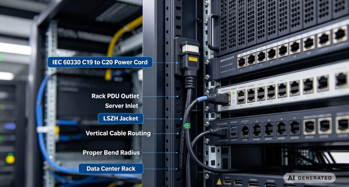
System integrators, panel builders, and procurement teams in data center projects rarely lose time because the server or PDU specification is wrong. They lose it when a standard 1.8-metre cordset leaves 1.5 metres of excess cable coiled behind a 42U rack, when a generic C19 connector loosens under vibration in a high-density cabinet, or when the cable jacket does not meet the LSZH requirement that the facility’s fire-safety concept assumes.
TPS Elektronik’s cable assembly services built to close that gap: IEC 60320 C19/C20 high-current cordsets with custom lengths, LSZH or PVC jacket selection, correct conductor gauge for 16A and 20A service. And documented crimp and electrical test—from a single rack build to a multi-site rollout.
1. What IEC 60320 C19/C20 actually specifies
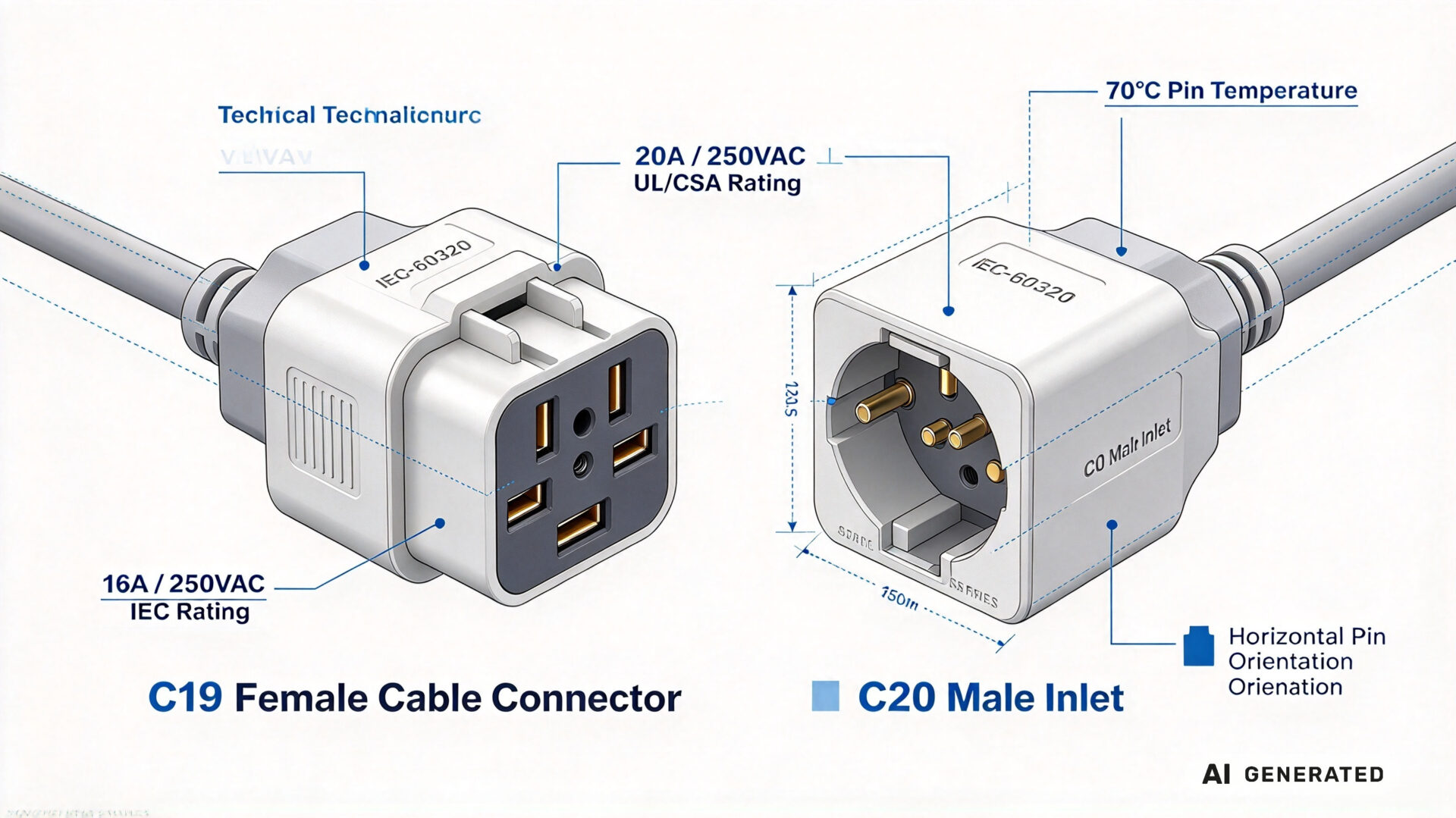
IEC 60320-1 defines the standard sheet for appliance couplers. The C19 connector is the female cable-mounted connector; the C20 is the corresponding male inlet on the equipment. They keyed so that a C19 cannot mated to a C14 inlet, and vice versa—a physical safeguard that prevents a 16A connector from used on a circuit rated for a lower current.
The C19/C20 pair is the standard high-current interface for rack PDUs, high-power servers, storage arrays, and UPS outlets. It uses a horizontal pin orientation and a rectangular body that distinguishes it from the smaller C13/C14 vertical-pin interface.
1.1 16A versus 20A: the IEC and UL/CSA difference
Under IEC 60320-1, the C19/C20 rating is 16A at 250VAC. Under UL 60320-1 and CSA C22.2 No. 60320-1, the same connector family certified for 20A at 250VAC. This is not a contradiction; it reflects different regional standards and test conditions. For a data center deployment, the practical consequence is that the connector’s current rating must matched to the branch circuit protection and the regional certification requirement—not simply to the connector’s IEC number.
A cordset labelled 16A may be perfectly adequate for a European 16A PDU branch, but the same cordset construction must reviewed against the 20A UL requirement if it deployed in a North American rack protected at 20A. The connector’s certification, the conductor gauge, and the overcurrent protection must be consistent.
1.2 70°C pin temperature and what it means for the cordset
Standard C19/C20 connectors rated for a pin temperature of 70°C, described in the standards as “for cold conditions.” The pin temperature rating is not the same as the cable jacket temperature rating. A cordset may use a cable rated to 70°C or higher, but the connector interface itself is the limiting element in a high-ambient cabinet.
In a hot-aisle or a densely packed PDU, the connector pin temperature can rise above the ambient because of contact resistance and adjacent load. The cordset design must therefore respect the 70°C connector limit, and the installation must avoid bundling current-carrying cordsets so tightly that the connector temperature exceeds its rating. This is an engineering constraint, not a procurement detail.
2. Why a standard C19 cordset fails in a high-density rack
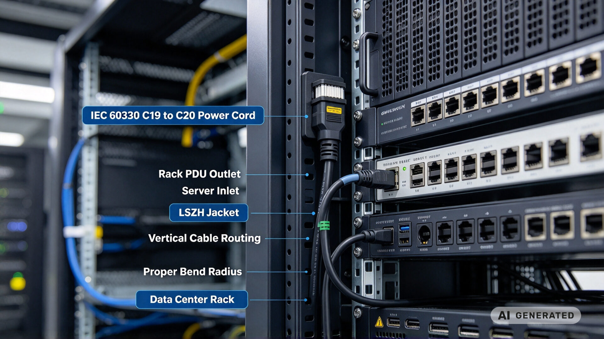
An off-the-shelf C19 cordset designed for a generic 1.8–2.5 metre run. In a high-density rack, that assumption breaks down in three predictable ways.
2.1 Length and cable management
A 2.5-metre cordset from a server to a vertical PDU leaves excess cable that must coiled, tied, and managed. The excess blocks airflow, adds weight to the cable management arm, and makes maintenance access harder. Conversely, a cordset that is 10cm too short forces the PDU into a suboptimal mounting position and wastes rack units. TPS manufactures cordsets to the measured length required for the specific rack layout, with a defined service loop where needed.
2.2 Conductor gauge and voltage drop
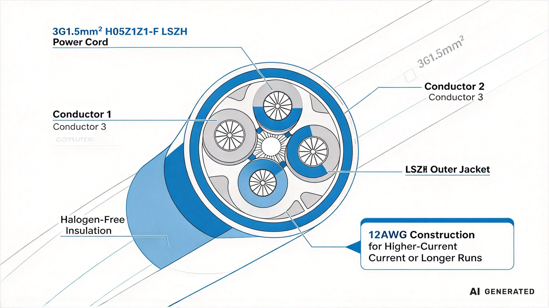
The standard European construction for a 16A C19/C20 cordset is 3G1.5mm² (three conductors, 1.5mm² each) in an H05VV-F or H05Z1Z1-F jacket. For 20A service or for longer runs where voltage drop matters, 12AWG construction used. The gauge selection is not interchangeable: a 1.5mm² conductor carrying 20A continuously will run hotter than a 12AWG conductor, and the connector pin temperature will rise accordingly.
The voltage drop calculation is straightforward. A 3-metre run of 1.5mm² copper at 16A has a round-trip resistance of approximately 0.07Ω, producing a drop of about 1.1V—less than 0.5% of 250V, which is acceptable. At 20A over a longer run, the drop becomes significant and the gauge must be increased. This is why the cordset should be specified with the actual load and length, not copied from a catalogue.
2.3 Jacket material: PVC versus LSZH
PVC (H05VV-F) is the lower-cost option and is mechanically robust. LSZH (H05Z1Z1-F, low smoke zero halogen) is the specification for data centers where the fire-safety concept assumes limited smoke and no corrosive halogen release in a fire event. The LSZH jacket has slightly different flexibility and bend behaviour, and the connector termination must be validated for the specific jacket compound. TPS offers both and documents the jacket type on the cordset label.
3. How TPS assembles a C19/C20 high-current cordset
TPS’s cable assembly workflow follows the IPC/WHMA-A-620 standard for cable and wire harness assemblies. For a C19/C20 high-current cordset, the critical process steps are conductor preparation, crimp termination, and electrical verification.
3.1 Cutting, stripping, and conductor preparation
The cable cut to the specified length with a tolerance defined by the rack layout. The outer jacket stripped to the dimension required by the connector’s strain relief, and the individual conductors stripped to the crimp barrel length. For LSZH jackets, the strip force and blade geometry adjusted because the halogen-free compound behaves differently from PVC. Conductor strands must not be nicked; a nicked strand reduces the current-carrying cross-section and creates a local hot spot.
3.2 Crimp termination and pull-test verification
The C19 connector terminals crimped to the conductors using a calibrated crimp tool and the terminal manufacturer’s specified crimp height. The crimp verified by pull-test on a sample basis, and the pull force must meet the terminal manufacturer’s specification. A crimp that is visually acceptable but under-crimped will develop contact resistance over time; a crimp that is over-crimped will fracture strands. Both failure modes detected by pull-test, not by visual inspection alone.
The connector housing then assembled and the strain relief is engaged. The cordset must withstand the specified pull force on the cable without transferring the load to the crimp terminals.
3.3 Electrical test and documentation
Every cordset electrically tested for continuity, correct polarity (line, neutral, protective earth), and insulation resistance between conductors and between conductors and the protective earth. For high-current cordsets, a contact resistance measurement on each conductor provides an early indication of a poor crimp. The test record accompanies the delivery and can be referenced in the data center’s commissioning documentation.
TPS’s broader cable assembly scope includes BNC connector assemblies for test and measurement, SMA connector assemblies for RF, and fiber optic cable assemblies for high-bandwidth links. The tested and documented cable assembly resource describes the quality workflow that applies across these product families.
4. Application guidance: server, PDU, and UPS connections
The same C19/C20 connector family used in three distinct connection scenarios, and each has a different cordset requirement.
- Server to rack PDU: The most common high-density connection. Length determined by the vertical distance between the server inlet and the PDU outlet, plus a service loop. Colour coding (blue for primary, red for redundancy) is a practical way to reduce maintenance errors.
- PDU to UPS: A higher-current link, often 20A or 32A depending on the UPS rating. The conductor gauge and connector certification must match the UPS output protection. This is the link where the 16A/20A regional difference is most likely to cause a compliance issue.
- UPS to wall or busway: Often a hardwired or specialized connector, not a C19/C20 cordset. If a C19/C20 is used here, the upstream protection and the connector rating must coordinated.
For high-density racks, a locking C19 variant (sometimes called a C19 lock) provides additional retention where vibration or accidental contact is a risk. TPS can supply locking and angled variants where the connector manufacturer’s certified version is available.
5. RFQ checklist
To streamline quotation and engineering review for a power cable for power supply using IEC 60320 C19/C20 connectors, provide the following:
- Connection points: Which end is C19 and which is C20, and whether a locking or angled variant is required
- Current and voltage: 16A or 20A service, and the regional certification requirement (IEC, UL, CSA)
- Conductor gauge: 3G1.5mm², 12AWG, or a specified cross-section based on load and length
- Jacket material: PVC (H05VV-F) or LSZH (H05Z1Z1-F), and any colour-coding requirement
- Length: Measured length per rack layout, with tolerance and service-loop requirement
- Test documentation: Continuity, polarity, insulation resistance, and contact resistance report
- Volume: Prototype rack quantity, series rollout volume, and delivery schedule
Providing these details reduces clarification cycles. TPS’s engineering team can support connector certification review, gauge selection, and length planning as part of the RFQ process.