

Custom 19-inch power cabinets | Engineering and RFQ guide
A custom pre-wired cabinet should arrive with a defined electrical architecture, accessible interfaces, and documentation that helps your team commission the system. For industrial power projects, the purchasing decision therefore extends beyond enclosure dimensions: it includes AC distribution, DC busbars, protective devices, cooling, safety functions, and responsibility for integration.
TPS Elektronik GmbH can support custom 19-inch cabinet solutions for global B2B customers, from selecting a suitable rack architecture to configuring wiring, monitoring, and project interfaces. The Sentinel platform provides a practical basis for that discussion. Explore the TPS 19-inch cabinet portfolio or discuss your pre-wired cabinet requirements with TPS before freezing the module layout.
1. Define what your pre-wired cabinet must include
For system integrators, the first decision is the boundary between factory wiring and site work. An empty rack, a cabinet with pre-wired distribution, and a fully populated power system represent different procurement scopes. Specify which power modules are supplied, installed, connected, and tested, alongside external cables, software, accessories, and commissioning support.
Panel builders need terminal locations, conductor identification, protective-earth connections, and service access. Electrical engineers need operating currents, fault-current assumptions, and safety interfaces. Procurement needs a clear bill of materials and acceptance criteria. Company owners and product managers should compare total implementation effort, including installation, documentation, maintenance, and later expansion.
A coordinated TPS cabinet solution can reduce the number of interfaces your team must resolve independently. Make that benefit measurable: define the connections remaining on site and the evidence required before shipment.
2. Choose the cabinet architecture around the module map
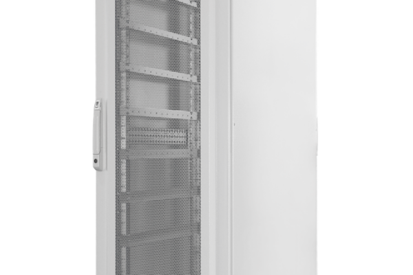
The Sentinel-X concept combines a 19-inch rack with a separate power-distribution section. This arrangement preserves rack space and allows distribution and module positioning to be developed independently. The distribution section can be positioned on either side, subject to the approved layout. It suits projects where dense power integration and service separation justify a wider footprint.
Sentinel-Y integrates distribution within the rack footprint. It is useful for simpler or space-constrained configurations, but part of the rack volume is allocated to electrical equipment. Compare the 48U cabinet architecture with the compact 24U integration concept. Select usable space after accounting for wiring, cooling, and maintenance clearances.
| Selection point | Series reference | What to confirm in the RFQ |
|---|---|---|
| Rack interface | 482.6 mm / 19-inch mounting width | Module depth, supports, mass, and available U positions |
| Input options | 400 / 480 VAC; 50 / 60 Hz; 3L + PE | Actual site supply and auxiliary-power requirements |
| Power envelope | 10–420 kW; up to seven 60 kW / 6U modules in a 48U configuration | Simultaneous loading, feeder capacity, and cooling |
| Fault-current rating | 10 kA reference; 65 kA custom option in series literature | Required SCCR at the specified voltage |
| High-current infrastructure | Custom DC busbar designs; series discusses 4,000 A and above | Continuous/peak current and verified thermal design |
These are series-level references, not a guaranteed combination for every build. Use the available cabinet options to establish a starting point; the quotation and approved drawings must define the delivered configuration.

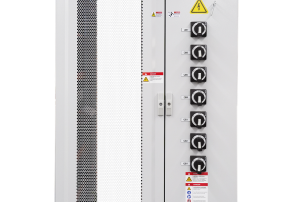
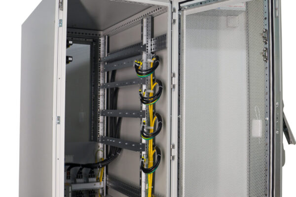
TPS cabinet example: the enclosure, operator controls, cable entry, and internal distribution should be reviewed together. Illustrated details are configuration examples; the agreed project drawing determines your supply.
3. Match AC distribution and DC busbars to real operating duty
A rack filled with compatible modules still needs a coordinated power path. Define the incoming disconnect, branch protection, contactors, terminals, protective earth, and DC connection arrangement. The series describes UL 489 circuit breakers, plated copper busbars, and segregated power and signal routing. Component selection must follow the final circuit ratings and destination requirements.
AC input: verify the simultaneous operating point
Do not combine the brochure’s highest output power with every listed input value. At 400 V and 600 A, three-phase apparent power is approximately 416 kVA before power factor, conversion losses, and auxiliaries. That cannot support 420 kW of continuous DC output. At 480 V, the calculation changes, but the approved continuous current and operating conditions still govern. Provide supply tolerances and the expected simultaneous load profile.
Discuss staged energization where several modules start together. For regenerative operation, confirm whether the facility can accept returned power and how upstream protection and shutdown behavior will be coordinated.
DC busbars: specify current, voltage, and connection geometry
Continuous current, pulse duration, ambient temperature, polarity, insulation clearances, and joint resistance determine the DC distribution design. A large copper cross-section alone does not establish the assembly rating. Request the connection arrangement, supported conductor sizes, tightening requirements, covers, and thermal verification. For parallel modules, define current sharing and branch isolation as well.
Include external load cables in the voltage-drop and heating review. State where cabinet responsibility ends and where customer wiring begins. This makes termination design and commissioning checks clearer, particularly when the equipment is supplied by several project partners.
4. Evaluate application fit before selecting accessories
For production test stands, the cabinet must support repeatable channel connections and quick service access. A 3U programmable DC supply integration example illustrates module-space planning; TPS can help evaluate suitable products or equivalent project solutions without locking the cabinet to one reference model.
For battery testing or energy-recovery applications, a 6U regenerative-load integration example raises additional questions about bidirectional energy flow, external DC isolation, and grid acceptance. For automation cabinets, auxiliary rails for control and monitoring may be supported by options such as the TPS Pro Series DIN-rail supplies. None of these components is automatically included; TPS can coordinate selection against your load and interface requirements.

Review the factory-wired interfaces in detail: protection, grounding, terminal access, control wiring, and operator functions. A clear connection schedule helps engineering and procurement compare the same scope.
5. Plan cooling, installation, and future maintenance
Size cooling from dissipated heat, not DC output power. Request losses for each operating mode, including regeneration, standby, and auxiliary equipment. Provide ambient limits, altitude, humidity, contamination, and room ventilation conditions. The series describes forced-air cooling and liquid-cooling integration options; final suitability depends on the selected modules and environment.
Airflow must reach the upper and lower module positions without recirculating hot exhaust. Cable bundles, blank panels, filters, and service covers influence that path. Agree on temperature monitoring, fan-failure response, alarm thresholds, and any automatic power reduction. Liquid-cooled projects also need defined coolant interfaces, leak response, and service responsibilities.
For installation, confirm overall dimensions, loaded mass, center of gravity, floor capacity, anchoring, and transport access. The Sentinel-X 48U reference is 1000 × 2200 × 1000 mm, but a custom cabinet requires its own approved drawing. Series frame-load claims should not be used as lifting or transport ratings.
Plan access to terminals and removable modules before purchase approval. Include cable bend radii, door swing, safe isolation points, and replacement paths. Spare U positions are only useful when distribution and cooling can also accommodate the planned expansion.
6. Confirm SCCR, safety functions, and certification scope
The supplied series literature describes UL 508A cabinet engineering and labeling, with references to NFPA 79 and ISO 13849. Ask TPS to confirm the certification route, assembly scope, applicable editions, marking, and supporting records for your destination. Listed components and a cabinet-level certification are different procurement evidence. IEC references in the brochure do not establish automatic equivalence between standards.
Supply the available fault current at the installation point. The reference cabinet tables state 10 kA SCCR; series literature describes a custom 65 kA option at 480 VAC. A higher rating depends on the complete component and protective-device combination. A breaker interrupting rating is not the cabinet’s SCCR. See UL guidance on determining SCCR for the underlying topic.
Door monitoring and a dual-channel emergency stop must be integrated into a defined safety function. The detailed tables reference Category 4 and PL d, while other brochure text discusses higher-rated safety relays. A relay rating does not establish the performance of the complete circuit. Specify the required safe state, reset behavior, stored-energy handling, and validation boundary. Official NFPA 79 and ISO 13849-1 resources help identify the relevant frameworks.

Ventilation and access protection are separate design questions. This cabinet door illustrates the enclosure concept; the picture alone does not establish a safety interlock, enclosure rating, or certified safety performance.
7. Compare suppliers by defined deliverables and acceptance evidence
A useful quotation separates mechanical hardware, distribution wiring, installed modules, control functions, documentation, and project services. Ask for option pricing where cooling, monitoring, remote display, or expanded safety interfaces change the scope. Confirm whether module procurement and integration are managed by TPS or retained by your team.
The datasheet includes an electrical schematic and manual in the reference supply. For your project, request the additional records that installation and maintenance require: layout drawing, bill of materials, terminal plan, cable identification, protective-device settings, and interface descriptions. Their format, language, and revision status should be agreed before production.
Specify a factory acceptance test that reflects your application. Candidate checks include wiring inspection, protective-earth verification, interlock and emergency-stop behavior, communications, alarms, and agreed functional loading. Thermal and electrical tests need defined conditions and acceptance limits. Confirm which checks are included, witnessed, or quoted separately.
For repeat orders, use an approved configuration baseline and a documented change process. Procurement should also confirm lead time after drawing approval, packaging, shipping destination, warranty terms, spare parts, and service arrangements. TPS can support project selection and customization; discuss these deliverables through its cabinet engineering and solution consultation page.
Ask each supplier to identify exclusions explicitly so your technical and commercial comparison uses the same boundary.
8. Send an RFQ that can become a comparable technical offer
A preliminary module list and electrical single-line diagram are often enough to start a technical discussion. Mark each requirement as mandatory, preferred, or open to an equivalent TPS solution. If some parameters remain undecided, identify who will close them during the design review.
- Application: operating modes, simultaneous load, duty cycle, quantity, and destination country.
- Modules: U-height, depth, mass, interfaces, heat losses, and customer-supplied equipment.
- Electrical: AC voltage/frequency, feeder capacity, fault current, DC voltage/current, polarity, and regenerative operation.
- Installation: footprint limit, access route, cable entry, ambient conditions, cooling, and expansion needs.
- Safety and controls: risk assessment, shutdown behavior, door monitoring, remote I/O, alarms, and required standards.
- Commercial scope: documents, FAT/SAT expectations, target delivery, packaging, and support requirements.
Reference the TPS cabinet range and attach your existing layout if available. The objective is a configuration that can be priced and approved with explicit interface ownership, not a quotation based only on rack height.
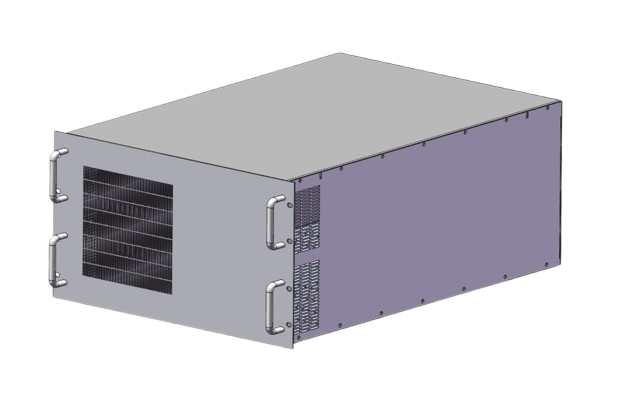
Cabinet planning includes the equipment mounted inside it. This 6U chassis is a separate integration example, not a standard cabinet accessory. Review 6U chassis integration considerations when defining module supports and service space.
9. Discuss your custom pre-wired cabinet with TPS
Bring your module list, site supply, and installation constraints. TPS can help assess the cabinet architecture, power-distribution concept, integration options, and project-specific documentation. Global B2B customers can request a product quotation or engineering consultation with a clear proposed supply boundary.
Request a custom cabinet solution from TPS or review 19-inch cabinet products for your RFQ.
10. FAQ: custom pre-wired cabinet procurement
Are power modules included in a pre-wired cabinet?
Only if the quotation includes them. Distribution wiring, module installation, DC connections, controls, and factory tests should each be defined. Customer-supplied modules require agreed interface data and responsibility for integration.
Should we select Sentinel-X or Sentinel-Y?
Choose around the electrical layout and usable rack space. Sentinel-X separates distribution from the rack; Sentinel-Y integrates it within the footprint. Compare access, module count, cooling, and expansion before choosing height.
Does every configuration have the same UL 508A or SCCR status?
No universal status should be assumed. Request the delivered assembly’s certification scope and marked ratings. Custom SCCR depends on the approved circuit and protection combination, with voltage explicitly stated.
Can we expand the cabinet later?
Yes, expansion can be planned, but available U positions alone are insufficient. Reserve feeder capacity, distribution connections, cooling, control channels, and structural capacity. Changes may also affect safety and certification evidence.
What if our specifications are incomplete?
Send the application, preliminary module list, supply data, destination, quantity, and schedule. Use the TPS cabinet consultation route to identify open decisions and develop a defined RFQ scope.