Data center architects and system integrators rarely fail because they lack a budget for servers. They lose resilience—and face unacceptable downtime risk. When the electrical power infrastructure beneath the IT load not designed to survive a single component failure without service interruption. A global financial data center operator, expanding their Tier III facility with a new high‑density server hall. Which faced exactly this challenge. Their existing power design could not guarantee concurrent maintainability for the new 30 kW per rack deployment. And the only off‑the‑shelf power shelves they evaluated required a compromise: either sacrifice rack space for redundancy, or sacrifice redundancy for density.
TPS Elektronik’s data center power design guide service resolved this dilemma. By engineering a custom, dual‑bus power shelf with integrated N+1 hot‑swap PSUs and a compact mechanical design, TPS delivered a power system that met the operator’s strict Tier III requirements while preserving every rack unit for revenue‑generating servers. This case study details how a mechatronic approach to power integration turned a potential single point of failure into a resilient, maintainable system.
1. The challenge: achieving Tier III resilience with standard components
The operator’s design brief was clear: each rack must support 30 kW of IT load with N+1 PSU redundancy at the shelf level. And the facility’s 2N power distribution to each rack must maintained. Off‑the‑shelf 1U CRPS power shelves offered the right form factor but lacked the current capacity to support a full 30 kW load without over‑provisioning, wasting precious rack units. Larger 2U shelves provided the power but consumed space that the operator could not afford to lose across 200 planned racks. The procurement team was caught between density and reliability, precisely the kind of trade‑off that TPS’s integrated design‑and‑build approach was created to resolve.
2. The TPS N+1 and 2N integration solution
TPS proposed a fully custom, rack‑level power integration service that addressed the electrical, mechanical, and thermal constraints simultaneously. The solution was a bespoke power shelf with an integrated N+1 PSU backplane and a copper busbar distribution system, all housed within a compact 2U form factor. This design approach mirrors the principles of integrated system engineering detailed in our resource on EMS mechatronics and precision machining.
2.1 Custom power shelf and busbar design
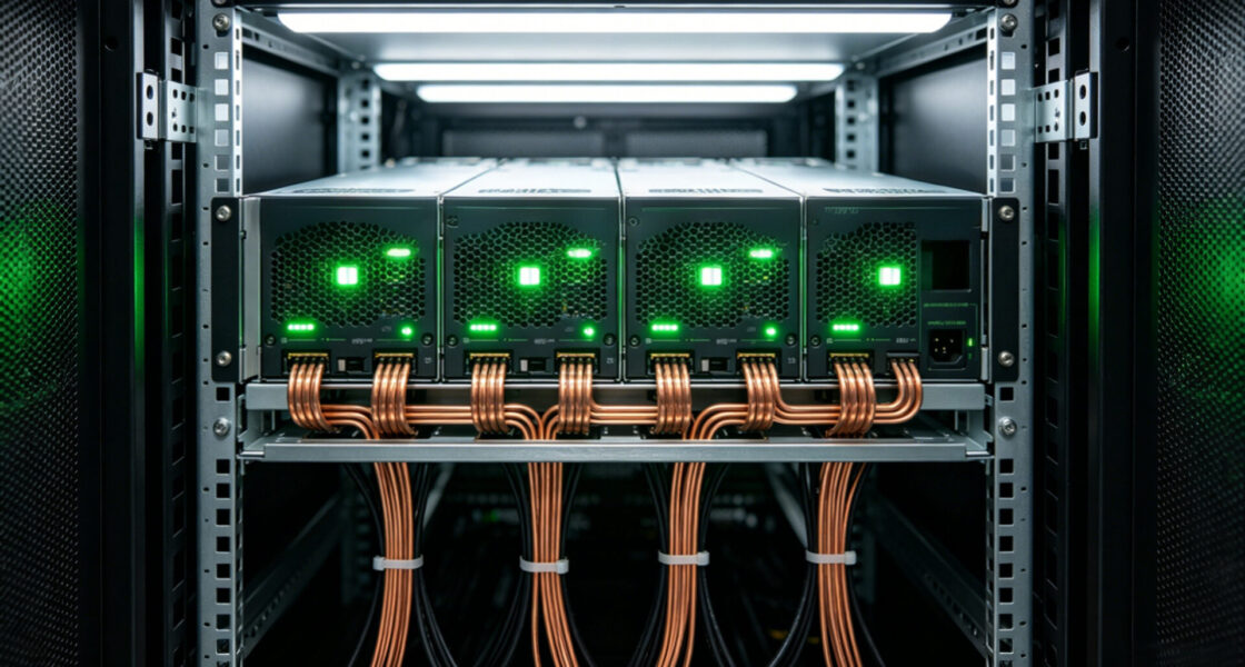
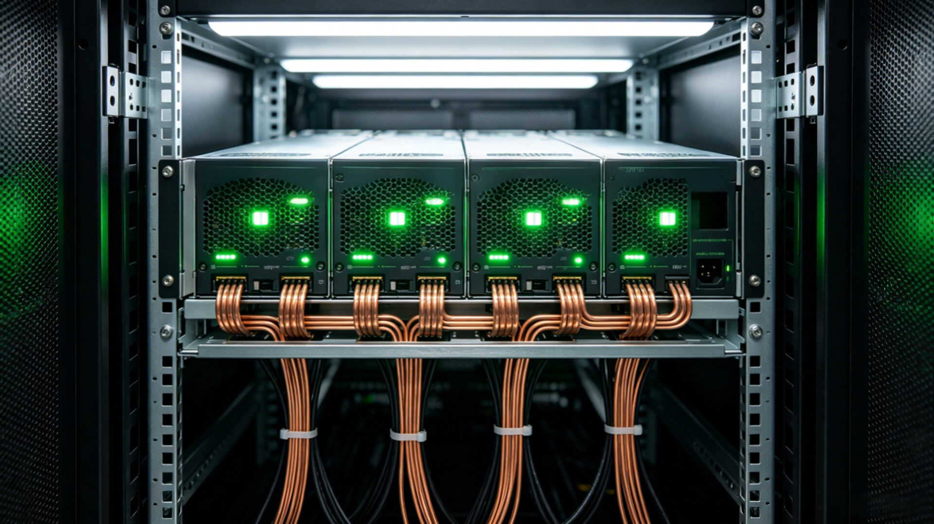
TPS engineers designed a 2U shelf capable of housing four 10 kW CRPS‑compatible PSU modules. In normal operation, three modules shared the 30 kW load, with the fourth serving as a hot‑spare in an N+1 configuration. The backplane integrated active OR‑ing MOSFETs. Which ensuring that a short‑circuit failure on any single module would not pull down the common 48 V bus. Low‑loss copper busbars, sized to limit voltage drop and temperature rise. Which distributed the power to the server bays below the shelf.
2.2 Hot‑swap and fault isolation
A critical requirement was the ability to replace a failed PSU without powering down the rack. TPS’s hot‑swap design included staggered pin connectors and inrush current limiting. Which allowing a technician to safely insert a new module into a live backplane. This feature directly supports the concurrent maintainability requirement of Tier III and higher data center designs.
2.3 2N failover architecture and testing
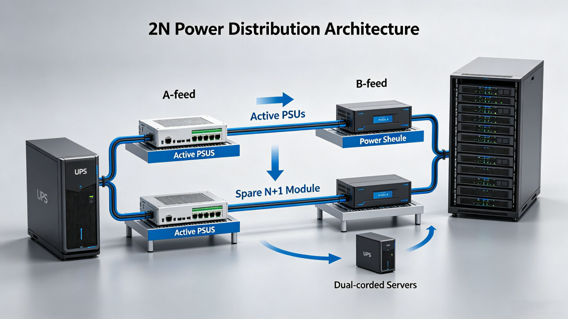
Each rack provisioned with two identical power shelves, fed from independent A and B power distribution paths. In the event of a complete failure of one path, the surviving shelf was capable of supporting the full 30 kW rack load without exceeding its N+1 redundancy rating. Before deployment, TPS performed a full‑scale failover test, simulating the loss of an entire A‑feed while monitoring the load transfer to the B‑feed. The integrated shelf maintained output voltage within ±1 % during the transient, with zero interruption to the simulated server load. This testing protocol is part of the broader commitment to delivering fault‑tolerant systems. Which is a core element of the EMS mechatronics for PLC control systems design philosophy.
3. Measurable results and operational impact
The deployment of TPS’s integrated power shelves across the new server hall delivered immediate operational benefits. The 2U shelf design saved the operator 400 rack units across the 200‑rack deployment. Enough space to accommodate an additional 10 fully populated server racks. The N+1 and 2N architecture eliminated any single point of failure in the power path, achieving the resilience target without compromise. For the procurement team, consolidating the design, manufacturing, and testing of the power system with a single partner. TPS—reduced supplier count and simplified the documentation required for the facility’s Tier III compliance audit. The full lifecycle support, from custom design to volume manufacturing. Which is a hallmark of the approach described in our guide to mechatronics from design integration to production.
4. RFQ checklist for redundant power integration
- Rack power target: Total DC load per rack (kW) and maximum U‑height available for power shelves.
- Redundancy model: N+1, 2N, or 2(N+1).
- Power architecture: 48 V DC bus, single or dual feed, and any requirement for integrated battery backup.
- PSU specifications: Preferred form factor (e.g., CRPS), per‑module wattage, hot‑swap requirement, and PMBus interface for monitoring.
- Compliance targets: Uptime Institute Tier level, regional safety standards (IEC 62368‑1, UL 60950‑1).
- Quantities and schedule: Prototype, pilot, and series volumes.
5. FAQ
What is the difference between N+1 and 2N redundancy?
N+1 provides one extra power module beyond what is needed to support the load, protecting against a single module failure. 2N provides two completely independent power paths, each capable of supporting the full load, protecting against a failure of an entire power feed.
Can TPS’s solution support a mix of AC and DC power distribution within the same rack?
Yes. TPS can design power shelves that distribute both 48 V DC for servers and 230 V AC for auxiliary equipment, with appropriate isolation and protection for each bus.
Does TPS provide the PSU modules themselves, or just the shelf integration?
TPS provides the complete integrated assembly, including the shelf, backplane, busbars, and PSU modules, all sourced and tested as a single system.
Where can I learn more about TPS’s broader mechatronics and integration capabilities?
Visit the TPS mechatronics service page or read our overview on mechatronics and robotics.