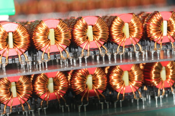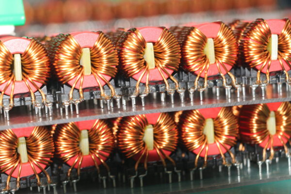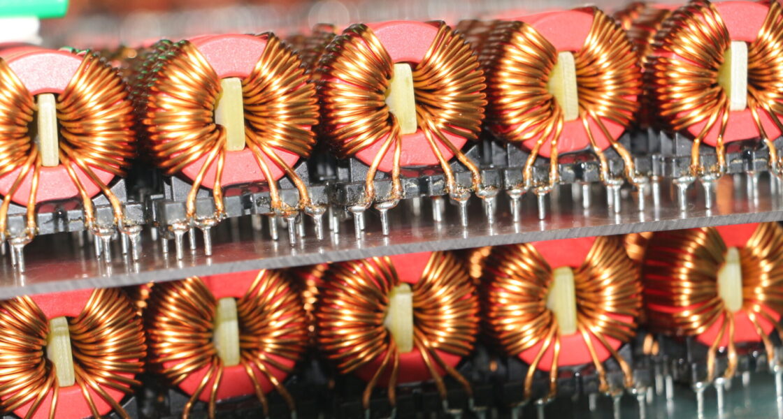
System integrators, panel builders, and procurement teams rarely fail because they lack a circuit design. They lose time—and budget. When the magnetic components in a high‑frequency GaN or SiC power converter fail to meet efficiency and EMI targets due to excessive AC winding losses. At switching frequencies above 500 kHz, conventional solid‑wire windings suffer from severe skin and proximity effects that increase AC resistance by an order of magnitude. Which turning the transformer or inductor into a heater rather than an efficient energy transfer element.
TPS Elektronik’s high frequency coil winding service addresses these losses at their physical root. By specializing in Litz wire winding and planar inductor construction optimized for the MHz switching regime, TPS provides custom magnetic components that maintain high Q factor and low AC resistance. Which enabling wide‑bandgap semiconductor designs to achieve their full efficiency and power density potential.
1. Why winding technology matters for GaN and SiC power supplies
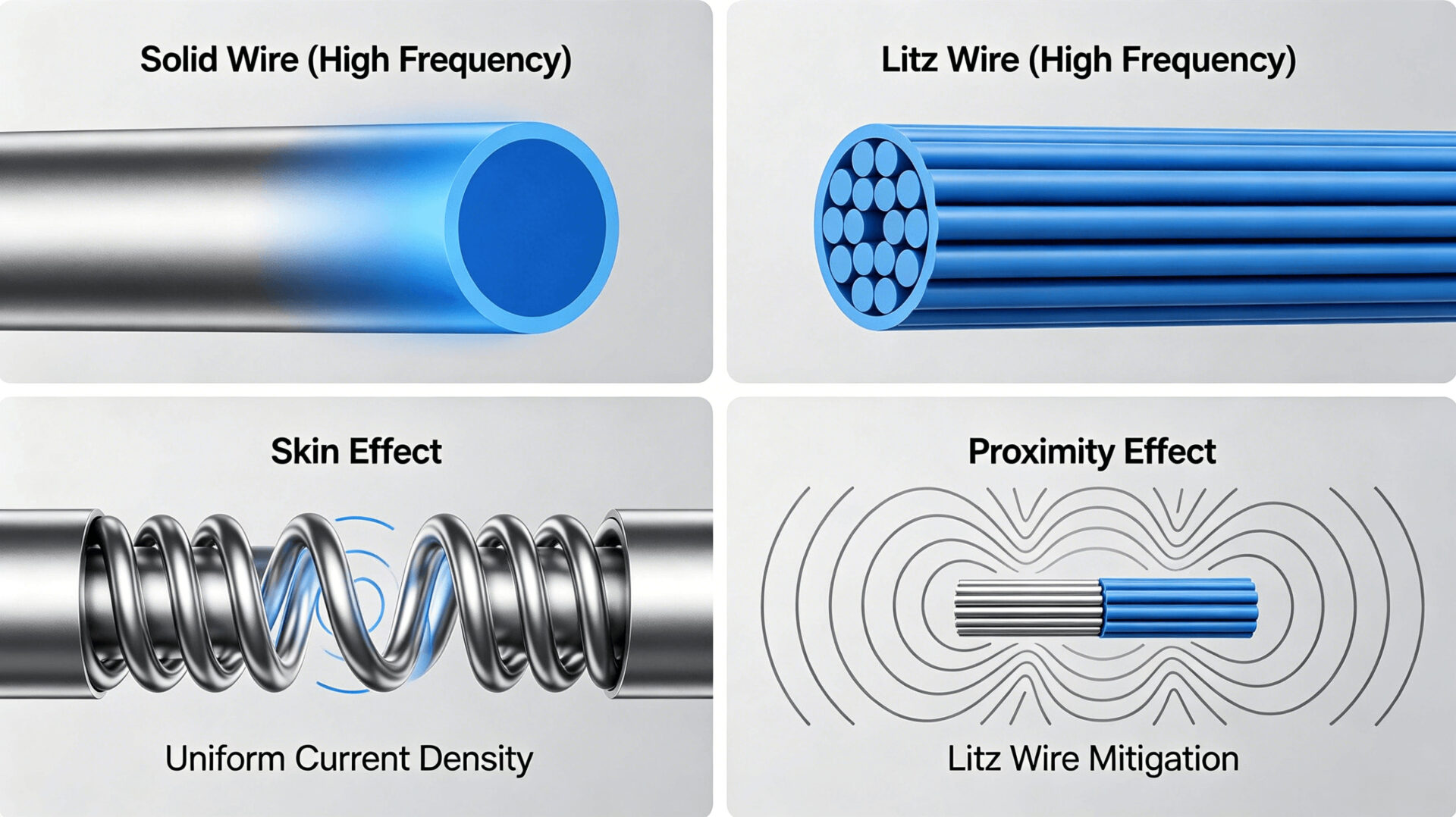
Wide‑bandgap semiconductors—GaN HEMTs and SiC MOSFETs—enable power converters to switch at frequencies from 500 kHz to several MHz, dramatically reducing the size of passive components. However, this frequency increase shifts the dominant loss mechanism in magnetic components from DC copper loss to AC winding loss. The skin effect confines current to the outer surface of a conductor. And the proximity effect induces eddy currents in adjacent turns, both of which increase the effective AC resistance (Rac) of the winding. At 1 MHz, a solid copper wire with a diameter of just 0.5 mm exhibits a skin depth of approximately 65 µm. Which meaning that most of the conductor cross‑section carries no current. The resulting Rac can five to ten times higher than the DC resistance.
High frequency coil winding techniques—specifically Litz wire construction and planar winding geometries. Which are the only practical solutions to this problem. TPS Elektronik’s winding service specifically engineered for these MHz‑domain applications. Which providing custom transformers and inductors that maintain efficiency and thermal performance at frequencies where standard magnetic components fail. For a broader context on how these coils integrate into production‑ready designs, see our resource on EMS winding goods and coil winding service.
2. Litz wire winding: design, strand count, and AC resistance reduction
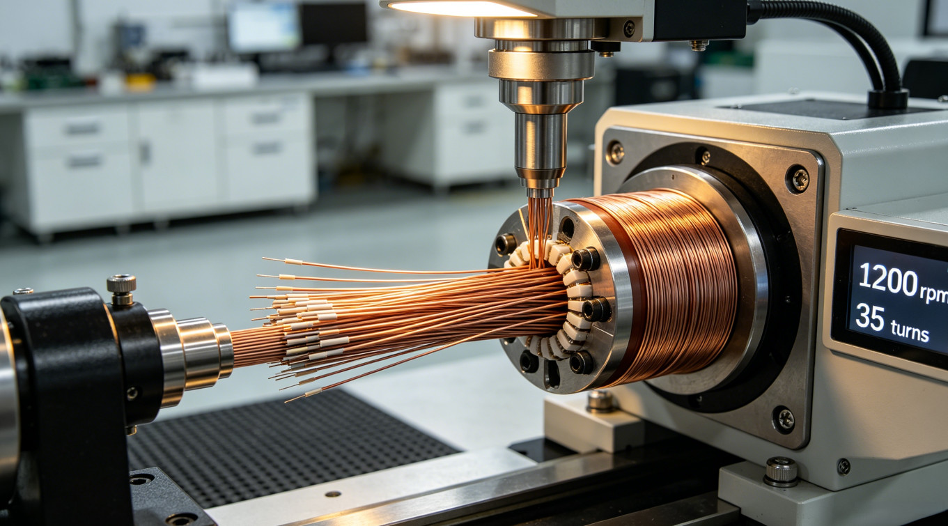
Litz wire is the primary solution for high‑frequency windings in the range of approximately 50 kHz to 2 MHz. It consists of multiple individually insulated strands twisted in a specific pattern that equalizes the current distribution among all strands, effectively increasing the conductive cross‑section at high frequency. The number of strands, their individual diameter. And the twisting pattern must be carefully selected based on the operating frequency and the winding geometry. TPS designs each Litz winding to the specific frequency, current waveform, and space constraints of the application.
2.1 Skin effect and proximity effect in high‑frequency windings
The skin effect is the tendency of high‑frequency current to flow near the surface of a conductor. The depth at which current density falls to 1/e of its surface value—the skin depth—is approximately 65 µm at 1 MHz for copper. The proximity effect, which often more severe than the skin effect in multi‑layer windings, arises from the magnetic field of adjacent turns inducing eddy currents. In a solid‑wire transformer winding with multiple layers, the proximity effect can increase Rac by a factor of 10 to 100 compared to Rdc. Which generating unacceptable heat and reducing efficiency.
Litz wire mitigates both effects. By subdividing the conductor into many fine strands. Each with a diameter smaller than the skin depth. And twisting them so that each strand occupies every radial position within the bundle over a short distance, the current forced to distribute uniformly. TPS selects the strand diameter, the number of strands, and the twist pitch based on the application’s fundamental frequency and the harmonic content of the current waveform, with design calculations supported by finite‑element analysis for critical applications.
2.2 Litz wire construction and selection for MHz operation
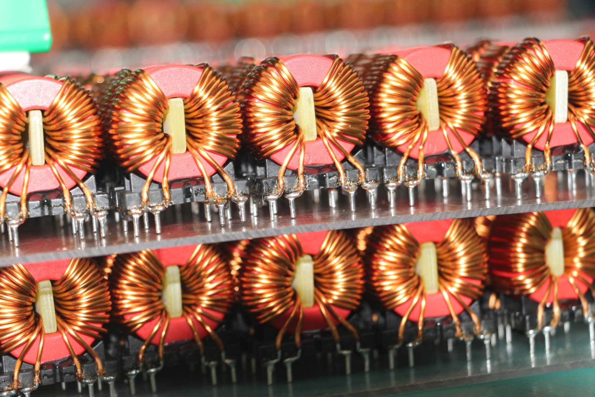
For a 1 MHz LLC resonant converter, a typical Litz wire specification might use 100 strands of 0.05 mm diameter (AWG 44), each coated with a solderable polyurethane insulation. TPS can handle Litz wire ranging from a few strands to over 1,000 strands, with overall diameters from under 1 mm to several millimeters. The wire is wound on high‑precision CNC machines with controlled tension to avoid strand breakage and insulation damage. The termination process—stripping the individual strand insulations and soldering or crimping to the terminal—is a critical step that TPS performs under documented procedures to ensure reliable connections. For a deeper look at wire insulation types, see our guide on wire insulation materials, types, and applications.
3. Planar inductor and transformer winding: low‑profile, high‑frequency performance
For converters operating above 1 MHz where Litz wire becomes less effective due to strand proximity effects, and for applications demanding the lowest possible component height, planar magnetic structures offer an alternative. A planar winding replaces the traditional round wire with flat copper traces on a printed circuit board or stamped copper lead‑frame. The windings arranged in multiple layers of the PCB, separated by thin insulation (typically FR‑4 or polyimide), and surround a low‑profile ferrite core.
Planar windings provide several advantages for high‑frequency operation. The flat conductor geometry reduces AC resistance compared to round wire because the current is distributed across a wider surface area. The inter‑layer spacing can precisely controlled, minimizing leakage inductance and providing excellent repeatability in production. TPS designs planar transformers and inductors for frequencies up to several MHz. Which using both PCB‑embedded windings and discrete planar cores. The mechanical integration of these components. Which including core clamping, thermal management, and termination. It is handled as part of the coil winding service, ensuring a production‑ready assembly. Examples of these production‑ready designs are showcased in our article on toroidal coils and production‑ready transformers.
4. Core materials and insulation for wide‑bandgap converters
The choice of magnetic core material is as critical as the winding technique. For GaN converters switching at 1 MHz and above, traditional power ferrites (such as 3C94 or N87) may exhibit excessive core losses. TPS selects core materials based on the specific frequency, flux density, and temperature requirements of the design. Low‑loss MnZn ferrites optimized for 1–3 MHz operation (such as 3F4, N49, or equivalent) are the standard choice for resonant inductors and transformers. For applications above 5 MHz, NiZn ferrites offer lower losses but at reduced permeability.
Insulation requirements are also more stringent at high frequency. The high dv/dt associated with GaN switching (often exceeding 100 V/ns) places stress on inter‑winding capacitance and insulation. TPS uses appropriate insulation materials. Which including triple‑insulated wire for reinforced isolation, polyimide tape for inter‑layer insulation. And margin tape for creepage compliance—all selected to meet the safety standards of IEC 62368‑1. For a detailed guide on magnetic fields and coil configurations, see our resource on Helmholtz coil and uniform magnetic field applications.
5. Electrical testing and quality assurance at high frequency
Standard LCR meters operating at 1 kHz or 10 kHz are inadequate for characterizing a winding designed for MHz operation. TPS performs electrical testing at the actual operating frequency of the component. This includes measurement of inductance, AC resistance (Rac). And Q factor at frequencies up to 2 MHz using precision impedance analyzers. Leakage inductance and inter‑winding capacitance are also measured, as these parameters directly influence the switching behavior of GaN and SiC converters.
Every high‑frequency winding produced by TPS undergoes 100 % electrical testing. The test report, provided with each production lot. Which includes all measured parameters, the test conditions, and a comparison to the specification. For safety‑critical applications, hipot testing at the required isolation voltage performed. This documented quality process is consistent with TPS’s broader EMS quality framework, as described in our overview of medical high‑frequency transformer coil winding.
6. Application examples: LLC resonant, phase‑shifted full‑bridge, and active clamp flyback
TPS high‑frequency winding services support the most common topologies in modern wide‑bandgap power conversion:
- LLC resonant converters: Require a resonant inductor and a transformer with tightly controlled leakage inductance and low AC resistance. TPS provides Litz‑wire‑wound resonant inductors and interleaved transformers optimized for operation from 500 kHz to 2 MHz.
- Phase‑shifted full‑bridge converters: Use an output inductor that must handle high DC bias with low AC loss. TPS designs gapped ferrite inductors with Litz wire windings to minimize both core and copper losses.
- Active clamp flyback converters: Popular in USB‑PD chargers up to 100 W, requiring compact transformers with low leakage inductance and high efficiency at frequencies above 300 kHz. TPS winds these transformers with fine Litz wire on small EFD or RM cores.
- GaN‑based class‑E and class‑Φ resonant inverters: For wireless power transfer and RF applications, TPS provides air‑core and ferrite‑core coils with precise inductance values and high Q factors.
These applications highlight the critical role of custom winding design in achieving the performance targets that wide‑bandgap semiconductors promise. By partnering with TPS, system integrators and procurement teams can access a single source for both the magnetic components and the broader EMS integration that brings a power supply from design to production.
7. RFQ checklist for high‑frequency coil winding
- Electrical specification: Topology (LLC, PSFB, flyback, etc.), switching frequency, nominal input/output voltage, power level.
- Inductance and turns ratio: Primary inductance, leakage inductance limit, turns ratio (NP:NS:NAux).
- Winding type: Litz wire (specify strand count/diameter if known) or planar (PCB‑embedded or discrete).
- Core preference: Core type and size (EE, EFD, RM, PQ, planar E‑I, etc.), or maximum mechanical envelope.
- Isolation requirements: Basic, reinforced, or functional; working voltage and required hipot test voltage.
- Target AC resistance: Maximum acceptable Rac at the switching frequency, if known.
- Quantities and schedule: Prototype, pilot, and series production volumes.
- Documentation: Required test reports, frequency‑domain measurements, and safety certificates.
8. FAQ
What is the highest frequency TPS can support for Litz wire windings?
TPS can provide Litz wire windings optimized for fundamental frequencies up to approximately 2 MHz. Above this frequency, planar winding techniques are typically recommended to minimize strand proximity effects within the Litz bundle.
Can TPS wind planar transformers on customer‑supplied PCBs?
Yes. TPS can either design the planar winding into a multi‑layer PCB or use a customer‑supplied PCB and assemble the core and mechanical hardware to complete the transformer.
How does TPS measure AC resistance at high frequency?
TPS uses precision impedance analyzers capable of measuring Rac and Q factor at frequencies up to 2 MHz, with Kelvin‑connected fixtures to eliminate lead resistance errors.
What core materials are available for high‑frequency designs?
TPS stocks a wide range of low‑loss MnZn ferrites (3F4, N49, and equivalents) optimized for 1–3 MHz operation, as well as NiZn ferrites for higher‑frequency applications.
Where can I learn more about TPS’s coil winding capabilities?
Visit the TPS winding goods service page, or read our technical guides on toroidal coils and chokes and medical high‑frequency transformer winding.