For system integrators, power electronics engineers, and procurement teams designing high-frequency switch-mode power supplies (SMPS), transformer winding losses are not a secondary concern. They are a primary constraint that determines efficiency, thermal performance, and reliability. At switching frequencies above 50 kHz, skin effect and proximity effect can cause the effective AC resistance of copper windings to rise several times above the DC value. Which generating heat that reduces efficiency and shortens component life.
TPS Elektronik’s copper transformer coil winding service addresses these losses through specialized winding techniques. Litz wire winding to distribute current across multiple insulated strands, and copper foil winding to maximize surface area and minimize AC resistance. From design support through automated winding, insulation, impregnation. And documented testing, TPS delivers production-ready transformers with the consistent high-frequency performance that modern SMPS designs demand.
1. Skin Effect and Proximity Losses: The Hidden Efficiency Killers in SMPS Transformers
In high-frequency SMPS transformers, winding losses are one of the primary sources of power dissipation Directly affecting thermal behavior, conversion efficiency, and component lifetime. While DC resistance losses are straightforward to calculate, AC winding losses. Which driven by skin effect and proximity effect. They are frequency-dependent phenomena that can cause the effective winding resistance to rise several times above its DC value.
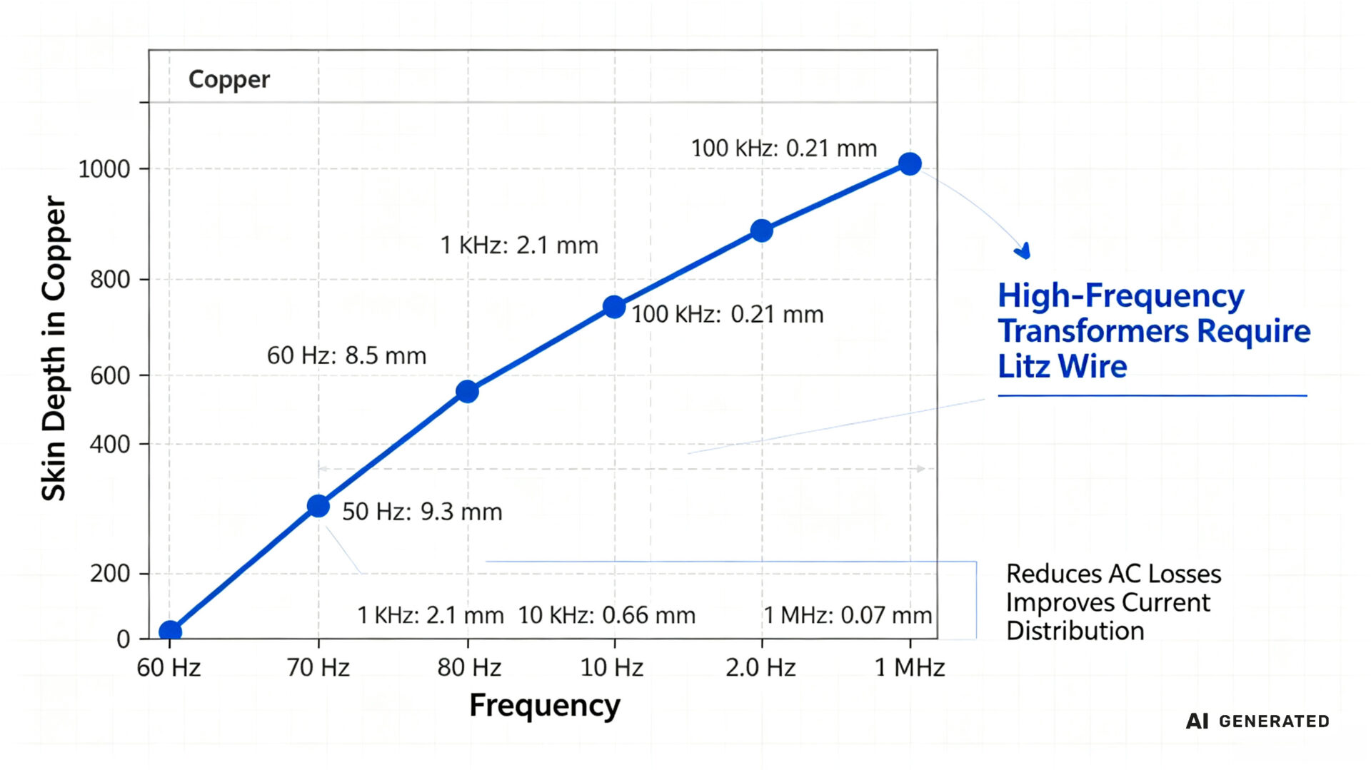
Skin Effect arises from the behavior of alternating current in a conductor. As AC frequency increases, current progressively concentrates toward the outer surface of the wire rather than flowing uniformly across its cross-section. The inner conductor volume becomes underutilized, effectively reducing the usable cross-sectional area and increasing the winding’s AC resistance. For copper at 20°C, skin depth is approximately 8.5 mm at 60 Hz, but drops sharply to around 0.21 mm at 100 kHz. This means that in a standard 1 mm diameter copper wire, nearly all current is confined to a thin outer shell at 100 kHz. The bulk of the conductor contributes almost nothing to current conduction.
Proximity Effect is a second, often underestimated, component of AC winding losses. It occurs when the alternating magnetic field generated by one winding induces eddy currents in a neighboring conductor. These eddy currents flow in circular paths within the conductor and produce additional ohmic losses—even in a conductor carrying no net current of its own. Unlike skin losses. Which affect each conductor individually, proximity losses increase with the number of winding layers, leading to higher losses in multi-layer designs.
In modern switched-mode power supplies—ranging from PC power supplies to solar inverters. Approximately one third of total system losses are attributable to inductive components. These losses result primarily from these two physical phenomena. The most effective solution at high frequencies is Litz wire, composed of multiple individually insulated strands. Each thinner than the skin depth at the target operating frequency. For high-current applications, copper foil winding provides an alternative approach by maximizing surface area and minimizing AC resistance.
2. Litz Wire Winding: Overcoming Skin Effect at High Frequencies
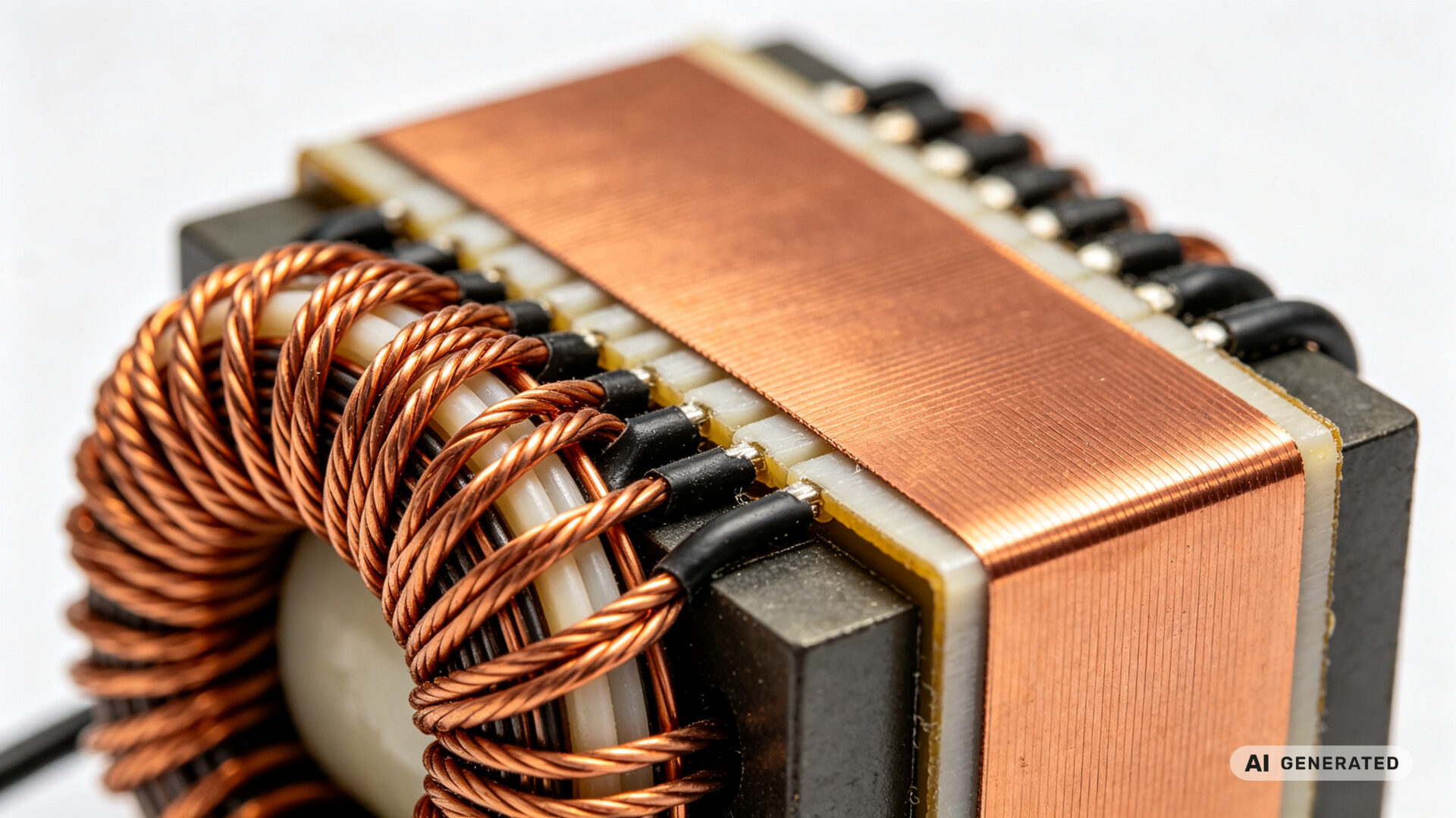
The Litz wire (from the German “Litzendraht,” meaning braided or stranded wire) is the industry-standard solution for minimizing skin effect losses in high-frequency transformer windings. By dividing a large conductor into tens or hundreds of individually insulated fine strands. Where each strand diameter is smaller than twice the skin depth (2δ)—current is forced to distribute evenly across all strands. This ensures a more uniform current distribution across the conductor cross-section and effectively eliminates skin effect losses.
For high-frequency SMPS transformers operating at 50 kHz to 1 MHz, Litz wire offers several decisive advantages:
- Reduced AC resistance: Litz wire can reduce high-frequency winding losses by 50–100% compared to traditional magnet wire
- Improved packing density: Litz wire can be formed into square, keystone, or rectangular shapes, optimizing the quality of circuits while minimizing AC resistance
- Proximity effect reduction: The individually insulated strands also reduce current losses from the proximity effect caused by nearby magnetic fields
- Broad frequency applicability: Litz wire is effective from approximately 10 kHz to 1 MHz, covering the operating range of most SMPS designs
However, the effectiveness of Litz wire depends critically on proper specification. Strand diameter must be smaller than the skin depth at the operating frequency. For 100 kHz, this means each strand must be less than approximately 0.42 mm in diameter. The number of strands, lay length, stranding type, and insulation covering all influence loss characteristics. Research has demonstrated that targeted optimization of these parameters can achieve substantial improvements in loss characteristics.
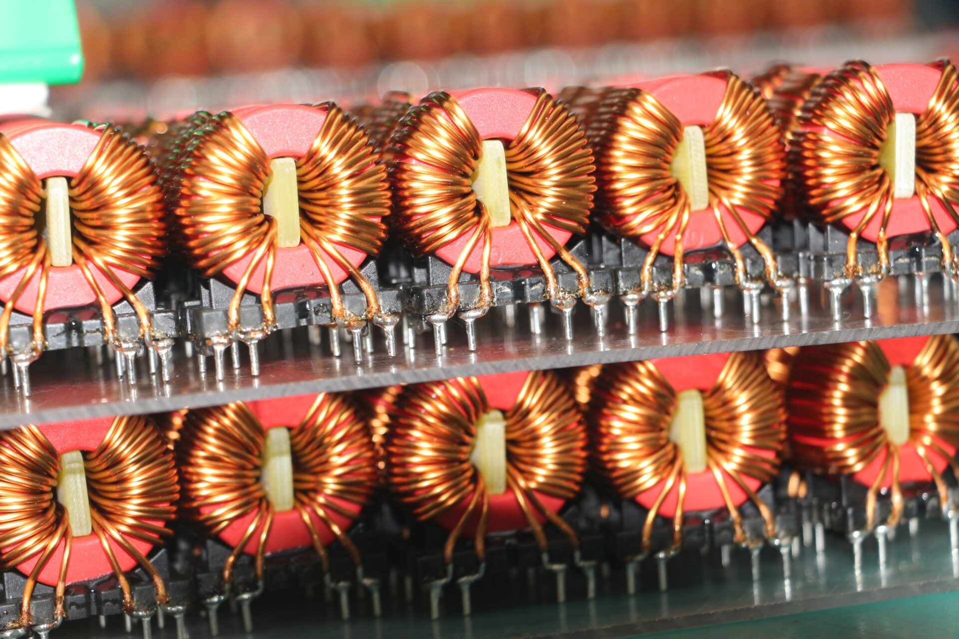
For high frequency copper coil winding applications, TPS Elektronik provides Litz wire winding with precisely specified strand configurations, optimized for the specific switching frequency and current requirements of each SMPS design. TPS operates a fleet of multi-axis automated winding machines capable of handling fine magnet wire down to AWG 40, with precision tension control to prevent wire stretch or insulation damage during winding.
3. Copper Foil Winding: Maximizing Surface Area for High-Current Applications
While Litz wire is the preferred solution for reducing AC losses in high-frequency windings, copper foil winding offers distinct advantages for high-current applications where window utilization and thermal performance are critical. Copper foils are used for better utilization of window area, providing increased copper space factor compared to Litz wire. Which offers lesser space factor due to added insulation between strands.
For high-current SMPS transformers—particularly those used in EV chargers, welding equipment, and large motor drives—copper foil winding delivers several key benefits:
- Superior space utilization: Foil windings maximize the copper fill factor within the transformer window, enabling higher power density
- Effective heat dissipation: Copper foil dissipates heat more effectively than magnet wire, reducing hot spots and improving thermal performance
- Reduced voltage stress: Foil winding facilitates a reduction in voltage stresses between turns in the winding
- Mechanical robustness: Foil-wound components offer increased mechanical strength compared to wire-wound components
- Cost effectiveness: Copper foil is significantly more affordable than Litz wire for high-current applications
For high-frequency transformer designs, a combination of Litz wire for primary windings and heavy-duty copper foil for secondary high-current output is often the optimal approach. This hybrid strategy leverages the strengths of both techniques: Litz wire minimizes AC losses in the primary where high-frequency switching currents flow. While copper foil handles the high DC and low-frequency currents in the secondary with minimal resistance and excellent thermal performance.
For copper foil transformer winding applications, TPS Elektronik provides precision foil winding with controlled tension and layer alignment. Which ensuring consistent electrical performance and mechanical integrity across production volumes. And TPS’s ribbon wound coil winding services utilize flat copper or aluminum wire (ribbon) to maximize the conductor’s surface area, significantly reducing AC resistance and allowing for exceptional current-carrying capacity within a compact footprint.
4. TPS Copper Transformer Coil Winding Capabilities
TPS Elektronik’s copper transformer coil winding service combines precision manufacturing, engineering support, and comprehensive quality assurance in a single integrated workflow. And TPS approaches EMS winding goods as a production-oriented workflow. From initial magnetic design and rapid prototyping to fully automated mass production.
Winding Capabilities:
- Litz wire winding: Multi-strand Litz wire with strand diameters optimized for specific switching frequencies from 10 kHz to 1 MHz
- Copper foil winding: Flat copper ribbon winding for high-current applications requiring exceptional space utilization and thermal performance
- Fine wire handling: Automated winding of magnet wire down to AWG 40 with precision tension control
- Multiple core geometries: Toroidal, EI, UI, and custom core shapes for diverse transformer designs
- Multi-axis CNC winding: Programmable pitch and controlled tension for uniform turns and reproducible coupling
Engineering and Design Support:
TPS provides comprehensive engineering support for custom transformer designs, including electromagnetic simulation to model core saturation, thermal hotspots, and high-frequency losses. TPS assists in selecting the optimal wire insulation materials and core materials based on frequency range, power level, and environmental requirements.
Insulation and Finishing:
- Inter-layer insulation with precision tape placement for creepage and clearance compliance
- Impregnation, potting, or overmoulding for vibration resistance, moisture protection, and acoustic performance
- Termination options including solder lugs, leadframes, and flying leads
Application Range:
TPS supports transformer projects ranging from power and signal designs to high-frequency SMPS applications. This is particularly relevant in medical, industrial, and power-electronics applications. Where electrical, mechanical, and documentation requirements often need to be aligned early. TPS’s custom coil winding service covers high-frequency power transformers, toroidal inductors, dv/dt filter chokes, and solenoid coils across industrial, medical, and automotive applications.
Request a copper transformer coil winding RFQ in 24–48 hours →
5. Quality Assurance: From Prototype to Production-Ready Transformers
For high-frequency SMPS transformers, quality is not just about meeting nominal specifications—it is about consistency across production volumes. A transformer that performs well on the bench but varies in AC resistance or leakage inductance from unit to unit creates field reliability issues that are expensive to diagnose and correct.
TPS Elektronik’s quality assurance for copper transformer coil winding includes:
Design Review and DFM: TPS engineers review designs during the quotation phase, providing DFM feedback to optimize winding geometry, insulation systems, and termination approaches for manufacturability and reliability. For EMS-driven projects, this typically includes alignment of electrical parameters (inductance, resistance, turns ratio), mechanical constraints (pin layout, mounting space), and test requirements.
In-Process Inspection:
- Winding tension monitoring during automated winding to detect variations that could affect insulation integrity or electrical performance
- Layer alignment verification to ensure consistent insulation and coupling
- Automated taping and inline measurement of Rdc, L, and Q
End-of-Line Testing:
- Inductance (L): Measurement at operating frequency to verify core assembly and winding integrity
- DC resistance (Rdc): Verification of winding resistance against specification
- Turns ratio: Verification of correct winding relationship for transformer applications
- Hipot (dielectric withstand): High-voltage testing to verify insulation integrity and isolation performance
- Optional testing: Environmental and acoustic screening for high-stress applications
Documentation:
- Material certificates: Full traceability of core materials, wire, and insulation components
- Test reports: Documented test results for each production batch
- First Article Inspection (FAI): Comprehensive dimensional and electrical reports for the first part of each production run
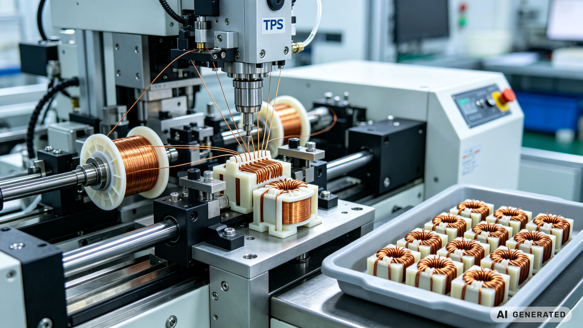
TPS Elektronik operates a fleet of automated winding machines with programmable tension, pitch control, and inline testing to support consistent and scalable production. This ensures that the first transformer and the thousandth transformer are electrically and mechanically identical.