For system integrators, electrical engineers, and procurement teams designing high-frequency DC-DC converters, the transformer is not a commodity. It is the component that determines conversion efficiency, EMI performance, and power density. A transformer with excessive leakage inductance wastes energy, generates heat, and radiates electromagnetic interference that can fail EMC testing. In resonant converters and soft-switching topologies, leakage inductance that is too high or too variable can prevent zero-voltage switching (ZVS). Which reducing efficiency and increasing stress on switching devices.
TPS Elektronik’s transformer winding manufacturing process addresses these challenges through two proven techniques: interleaved winding to minimize leakage inductance. And Litz wire winding to reduce high-frequency losses. From design support through automated CNC winding, insulation, impregnation, and documented testing, TPS delivers production-ready magnetic components with the consistent performance that high-frequency DC-DC converters demand.
1. Leakage Inductance: The Hidden Performance Killer in DC-DC Converters
Leakage inductance is the magnetic flux that does not couple between the primary and secondary windings of a transformer. In an ideal transformer, all flux links both windings. In the real world, some flux leaks through the air or insulation between windings. Which creating a series inductance that appears in the circuit model.
For high-frequency DC-DC converters, leakage inductance has several detrimental effects:
- Energy loss: Leakage inductance stores energy that must be dissipated or recovered, reducing converter efficiency
- Voltage spikes: When switching devices turn off, the energy stored in leakage inductance creates voltage transients that stress semiconductors and increase EMI
- EMI generation: The ringing caused by leakage inductance interacting with parasitic capacitances radiates electromagnetic interference
- Soft-switching failure: In resonant converters and LLC topologies, leakage inductance that is too high or inconsistent prevents ZVS, reducing efficiency
The challenge is particularly acute at higher switching frequencies, where even small leakage inductances represent significant impedance. As power density demands increase and converters push into the hundreds of kilohertz or megahertz range, leakage inductance becomes a primary design constraint.
For procurement teams and engineers evaluating transformer winding manufacturing process capabilities, the ability to consistently achieve low leakage inductance is a key differentiator. TPS Elektronik’s approach—combining interleaved winding geometry with Litz wire—addresses this challenge at both the structural and material levels.
2. Interleaved Winding: The Solution to Leakage Inductance
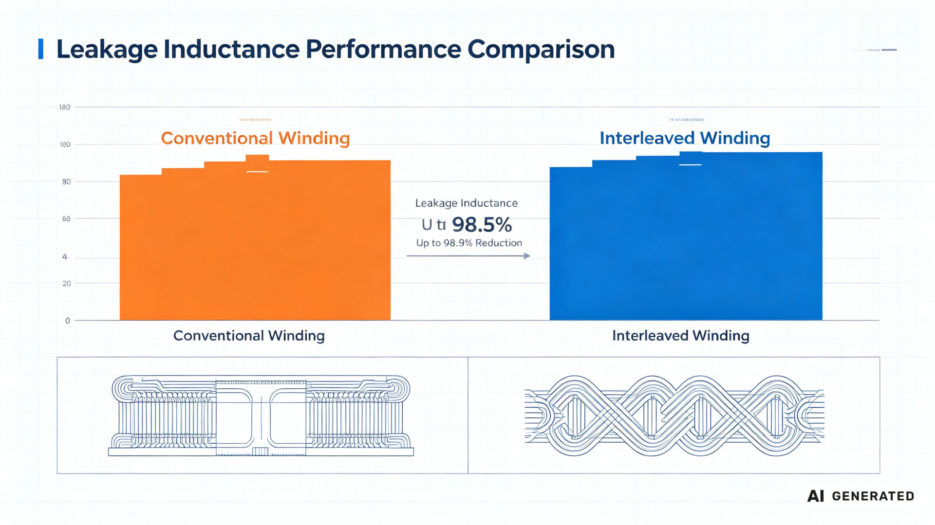
Interleaved winding is a transformer construction technique where primary and secondary winding segments are alternately layered, rather than placed as discrete blocks. This arrangement maximizes magnetic coupling between the windings and minimizes the flux that escapes as leakage.
In a conventional winding arrangement, the primary and secondary windings are wound as separate blocks on the bobbin. The magnetic field between these blocks creates significant leakage flux. In an interleaved design, the primary winding is split into sections, and the secondary winding placed between them—or vice versa. Which creating a structure where every primary turn is magnetically close to a secondary turn.
The benefits of interleaved winding for low leakage inductance transformer design are substantial:
- Up to 98.9% leakage inductance reduction: Research has demonstrated that interleaved winding can reduce leakage inductance by nearly two orders of magnitude compared to conventional winding designs
- Improved coupling: Tighter magnetic coupling means more efficient energy transfer and less stored energy in the leakage path
- Better load regulation: Lower leakage inductance reduces voltage drop under load. Which improving regulation across the operating range
- Reduced EMI: Less ringing at switching transitions means lower radiated and conducted emissions
Interleaving can be implemented in multiple configurations—primary split, secondary split, or fully interleaved layers—depending on the specific transformer requirements. For flyback converters, where leakage inductance directly affects the voltage spike across the primary switch. Which interleaved winding is particularly valuable.
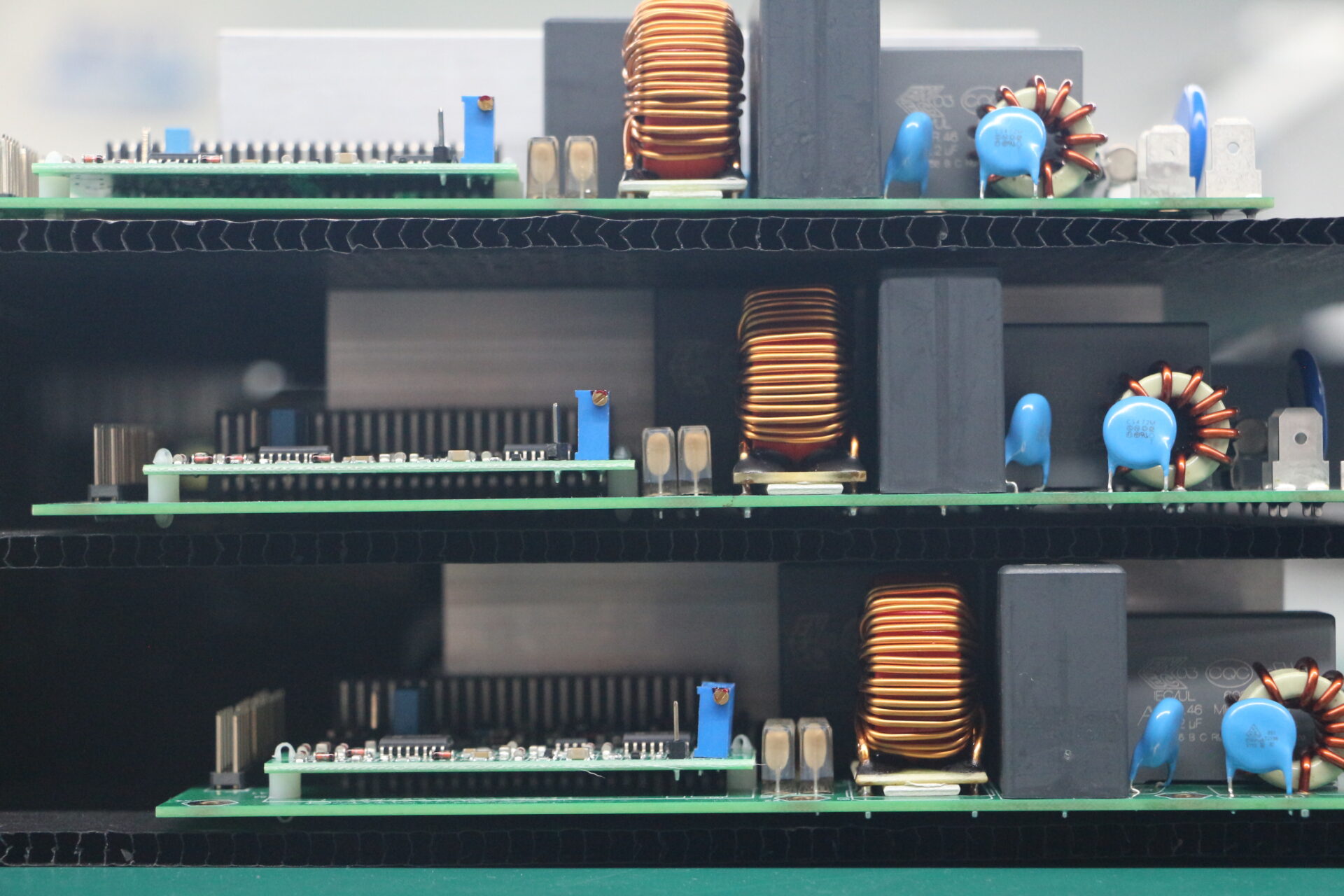
TPS Elektronik’s multi-axis CNC winding machines are capable of producing complex interleaved winding patterns with the consistency required for series production. The winding program, once validated, delivers identical winding geometry on every unit—a level of repeatability that manual winding cannot achieve.
3. Litz Wire: Overcoming Skin and Proximity Effects at High Frequencies
At high switching frequencies, conventional solid wire exhibits skin effect—the tendency of AC current to concentrate near the conductor surface, effectively reducing the usable cross-sectional area and increasing resistance. Proximity effect—the interaction of magnetic fields between adjacent conductors—further increases AC resistance, particularly in tightly wound transformer coils.
Litz wire (from the German “Litzendraht,” meaning braided or stranded wire) addresses these losses by using multiple individually insulated strands woven or braided together in a specific pattern. Each strand is thin enough that skin effect is minimal at the operating frequency, and the transposition of strands ensures that each strand occupies different positions within the bundle. Which equalizing current distribution and minimizing proximity effect losses.
For high-frequency DC-DC transformer applications, Litz wire offers several advantages:
- Reduced AC resistance: Litz wire can reduce high-frequency winding losses by 50% or more compared to solid wire of the same cross-sectional area
- Lower temperature rise: Reduced losses mean less heat generation, improving transformer reliability and allowing higher power density
- Better efficiency: Lower winding losses translate directly to higher converter efficiency—particularly important in applications where every percentage point matters
- Flexibility in design: Litz wire can specified with different strand counts, strand diameters, and insulation types to match specific frequency and current requirements
The selection of Litz wire parameters—strand count, strand gauge, and twist pitch—must optimized for the specific switching frequency and current waveform. TPS Elektronik’s engineering team provides DFM (Design for Manufacturing) feedback to ensure that the wire specification matches both electrical requirements and production feasibility.
For isolated DC-DC transformer winding applications, the combination of interleaved geometry and Litz wire addresses both magnetic and conductor losses. Which delivering transformers that achieve both low leakage inductance and low AC resistance.
4. The TPS Transformer Winding Manufacturing Process
TPS Elektronik’s transformer winding manufacturing process combines automated precision winding, comprehensive quality control. And integration with broader EMS capabilities to deliver production-ready magnetic components.
Engineering and Design Support:
- Core and wire selection: Guidance on ferrite or powder core materials, wire gauges, and insulation systems based on application requirements
- Interleaved winding geometry: Design of primary/secondary layer arrangements to minimize leakage inductance while maintaining manufacturability
- Litz wire specification: Determination of strand count, gauge, and insulation for optimal high-frequency performance
- Creepage and clearance planning: Margin tape placement and bobbin design to meet IEC 62368-1 and other safety standards
Automated Winding:
- Multi-axis CNC winding: Precise wire placement with dynamically controlled tension to prevent wire stretch and insulation damage
- Interleaved winding capability: Complex layer sequences with consistent interleaving across production volumes
- Litz wire handling: Specialized winding equipment capable of handling Litz wire without damaging the individual strand insulation
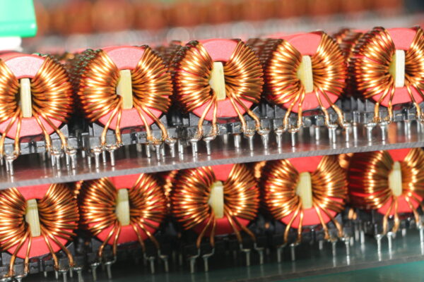
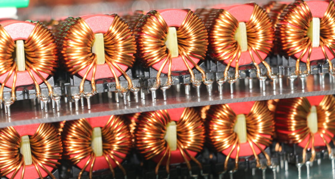
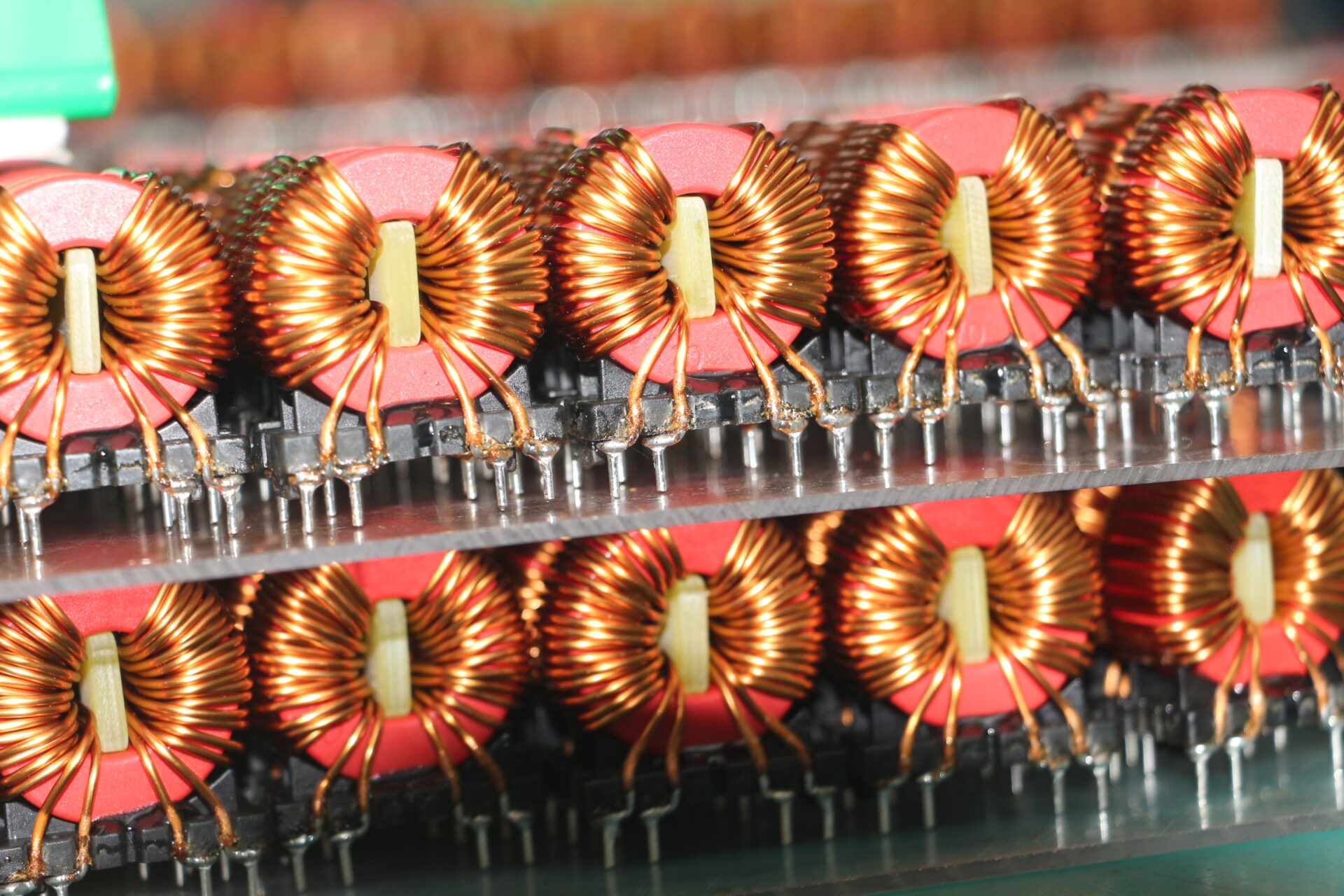
- Toroidal and bobbin winding: Flexible winding platforms for different core geometries and form factors
Insulation and Impregnation:
- Inter-layer insulation: Precise placement of margin tape and insulation materials to meet creepage requirements
- Impregnation and potting: Optional encapsulation to improve mechanical stability, thermal performance, and environmental protection
- Triple-insulated wire (TIW): Available for applications requiring reinforced isolation without additional insulation layers
Termination and Assembly:
- Pin and leadframe integration: Termination of winding ends to pins, leads, or terminals ready for PCB assembly
- Custom connectors: Integration of custom connectors or wire harnesses as required
TPS Elektronik’s coil winding service operates as a production-oriented workflow, not a prototype-only capability. Once a winding program is validated, the same process is repeatable across production volumes—ensuring that the first transformer and the thousandth transformer are electrically and mechanically identical.
5. Quality and Testing: Ensuring Consistent Performance
For high-frequency DC-DC converter transformers, quality is not just about meeting nominal specifications—it is about consistency across production volumes. A transformer that performs well on the bench but varies in leakage inductance or winding resistance from unit to unit creates field reliability issues that are expensive to diagnose and correct.
TPS Elektronik’s quality assurance for transformer winding manufacturing includes:
In-Process Inspection:
- Winding tension monitoring during automated winding to detect variations that could affect insulation integrity or electrical performance
- Layer alignment verification to ensure interleaved geometry is consistent from unit to unit
- Insulation placement inspection to verify margin tape and inter-layer insulation are correctly positioned
End-of-Line Testing:
- DCR measurement: Verification of DC resistance against specification to detect variations in wire gauge or winding tension
- Inductance (L) and Q factor: Measurement at the operating frequency to verify core assembly and winding integrity
- Polarity test: Verification of correct winding orientation for proper phase relationships in the converter circuit
- Hipot (dielectric withstand): High-voltage testing to verify insulation integrity and isolation performance
- Insulation resistance (IR): Measurement of insulation resistance to detect contamination or insulation damage
- Surge testing: Optional test to detect turn-to-turn insulation weakness
Documentation:
- Material certificates: Full traceability of core materials, wire, and insulation components
- Test reports: Documented test results for each production batch, including DCR, L/Q, hipot, and IR values
- Serialization: Unique identifiers on each transformer for traceability to production records and test results
For high efficiency DC-DC converter transformer winding applications, this quality framework provides the confidence that every transformer meets the required specifications—from the first prototype through high-volume production.
Request a transformer winding manufacturing RFQ in 24–48 hours →