For system integrators, panel builders, and electrical engineers working with industrial temperature measurement, the cable connecting an RTD or thermocouple sensor to the control system is not a passive component—it is an active part of the measurement chain. A poorly chosen or improperly assembled cable can introduce errors that compromise process control, product quality, and safety.
TPS Elektronik’s sensor cable assembly service delivers shielded, precision-terminated cables for RTD and thermocouple temperature sensors—engineered to preserve signal integrity in electrically noisy industrial environments, with documented quality and full traceability from prototype to production.
1. The Temperature Measurement Challenge: Noise, Distance, and Accuracy
Industrial temperature sensors—RTDs (Resistance Temperature Detectors) and thermocouples—produce relatively weak electrical signals that are highly susceptible to electromagnetic interference (EMI) from nearby equipment. A 100 Ω Pt RTD has a temperature coefficient of only 0.385 Ω/°C at 0 °C, meaning every 0.385 Ω of uncorrected loop resistance translates directly into a 1 °C measurement error. Thermocouples generate millivolt-level signals that are even more vulnerable to noise pickup.
In modern factory automation environments, the sources of electrical noise are everywhere: variable frequency drives (VFDs), motor starters, contactors, welding equipment, and radio transmitters all generate electromagnetic fields that can couple into unshielded sensor cables. An unshielded RTD lead can act as an antenna, coupling radio-frequency interference (RFI) into the measurement signal.
For system integrators and electrical engineers, the challenge compounded by cable length. Sensors often located hundreds of meters from the control cabinet or PLC, and long cable runs provide more opportunity for noise pickup and signal degradation.
The solution lies in a combination of factors: shielded cable construction, twisted pair geometry, proper grounding practices, appropriate wire configuration, and precision termination. TPS Elektronik’s sensor cable assembly service addresses each of these factors, delivering cables that preserve signal integrity from sensor to controller.
2. Shielding: Protecting the Weak Signal from Electrical Noise
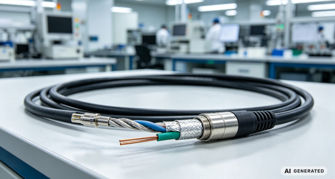
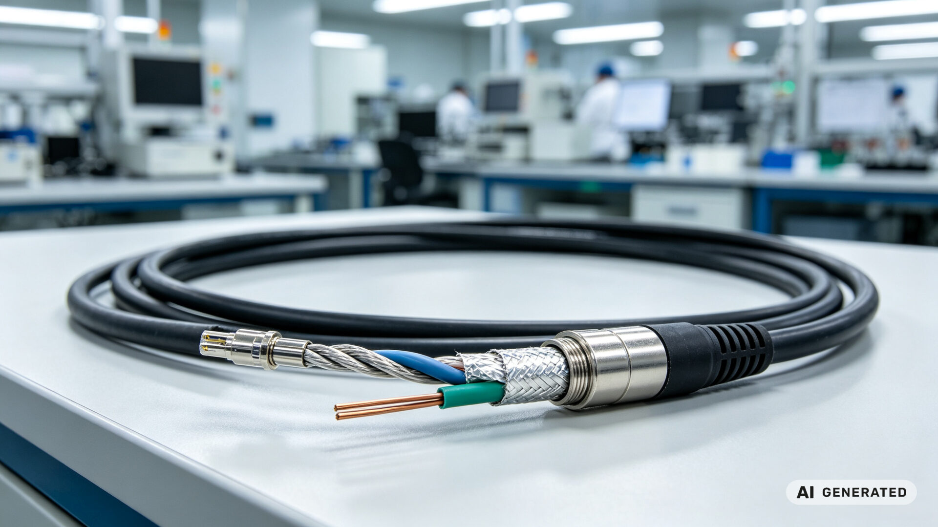
Shielding is the first line of defense against electrical noise in temperature sensor cables. A shield—typically a foil layer, a braided copper mesh, or both—surrounds the signal conductors and intercepts electromagnetic fields before they can couple into the sensor signal.
For RTD and thermocouple applications, there are several shielding options:
- Foil shielding with a drain wire: An aluminum/polyester foil tape wrapped around the conductors, with a bare copper drain wire in contact with the foil. Foil shielding provides 100% coverage and is effective against electrostatic fields.
- Braided copper shielding: A woven mesh of tinned copper wires provides excellent low-resistance shielding and mechanical durability. Braided shields offer 85–95% coverage and are effective against both electrostatic and electromagnetic fields.
- Combined foil and braid shielding: For the most demanding environments, a foil shield overlaid with a braided shield provides superior protection against both low-frequency and high-frequency interference.
Industrial standards such as IEC 60584-3 cover extension and compensating cables for thermocouples, including shielding requirements. While IEC 60751 for RTDs does not explicitly mandate shielding, the standard’s accuracy requirements can only maintained in electrically noisy environments with proper shielding practices. Leading automation manufacturers including Allen‑Bradley, Honeywell, Siemens, and Omega Engineering all recommend shielded twisted-pair cable for RTD connections.
For shielded sensor cable applications, TPS Elektronik offers cables with foil shielding, braided shielding, or combined shielding—selected based on the specific electromagnetic environment and the sensitivity of the measurement.
3. Twisted Pairs: Reducing Magnetic Field Coupling
Twisting the signal conductors together is a simple but highly effective technique for reducing magnetic field coupling. When two wires twisted, the loop area between them is minimized, and any magnetic field that couples into one twist cancelled by the opposite coupling in the adjacent twist.
For RTD and thermocouple applications, shielded twisted-pair cable is the industry standard. The twisted pair provides rejection of magnetic fields, while the shield provides rejection of electric fields. Together, they form a robust defense against most common sources of industrial EMI.
The benefits of twisted-pair construction for sensor cables include:
- Up to 60 dB reduction in magnetic field induction: Twisted pairs dramatically reduce the pickup of magnetic fields from adjacent conductors and equipment
- Common-mode noise rejection: Any noise that is coupled equally into both conductors appears as a common-mode signal that can be rejected by the differential input of the measurement instrument
- Consistent impedance: Twisted pairs provide a defined, consistent impedance that maintains signal integrity over long cable runs
For thermocouple applications, twisted thermocouple extension lead wire must be used to maintain the thermocouple’s accuracy over distance. The extension wire must be of the same thermocouple alloy type as the sensor (e.g., KX for Type K thermocouples) to avoid introducing additional thermoelectric voltages.
4. Grounding the Shield: One Point or Multiple?
While shielding protects against electric fields, improper shield grounding can introduce more noise than it removes—through ground loops that inject 50/60 Hz power-line noise onto the signal conductors.
The standard practice for RTD and thermocouple circuits is to ground the shield at one end only—typically at the control room, PLC, or acquisition instrument end—and leave it floating at the sensor end. This single-point grounding prevents ground loops while still providing effective shielding.
Key grounding guidelines for sensor cable assemblies:
- Apply the shield with low resistance, enveloping the cable by 360° at the entry point into the control cabinet
- Earth the shield conductively at the entry point into the control cabinet or at the terminal connection point
- Avoid unshielded cable lengths greater than 50 cm
- For grounded sensors: ground the shield at the sensor end
- For ungrounded sensors: ground the shield at the transmitter end
The shield should be terminated with a 360° low-impedance connection to the ground reference—a pigtail connection is not sufficient for high-frequency noise suppression. TPS Elektronik’s sensor cable assembly service includes proper shield termination options, with drain wires configured for single-point grounding per customer specifications.
5. Wire Configuration: 2-Wire, 3-Wire, and 4-Wire RTD Connections
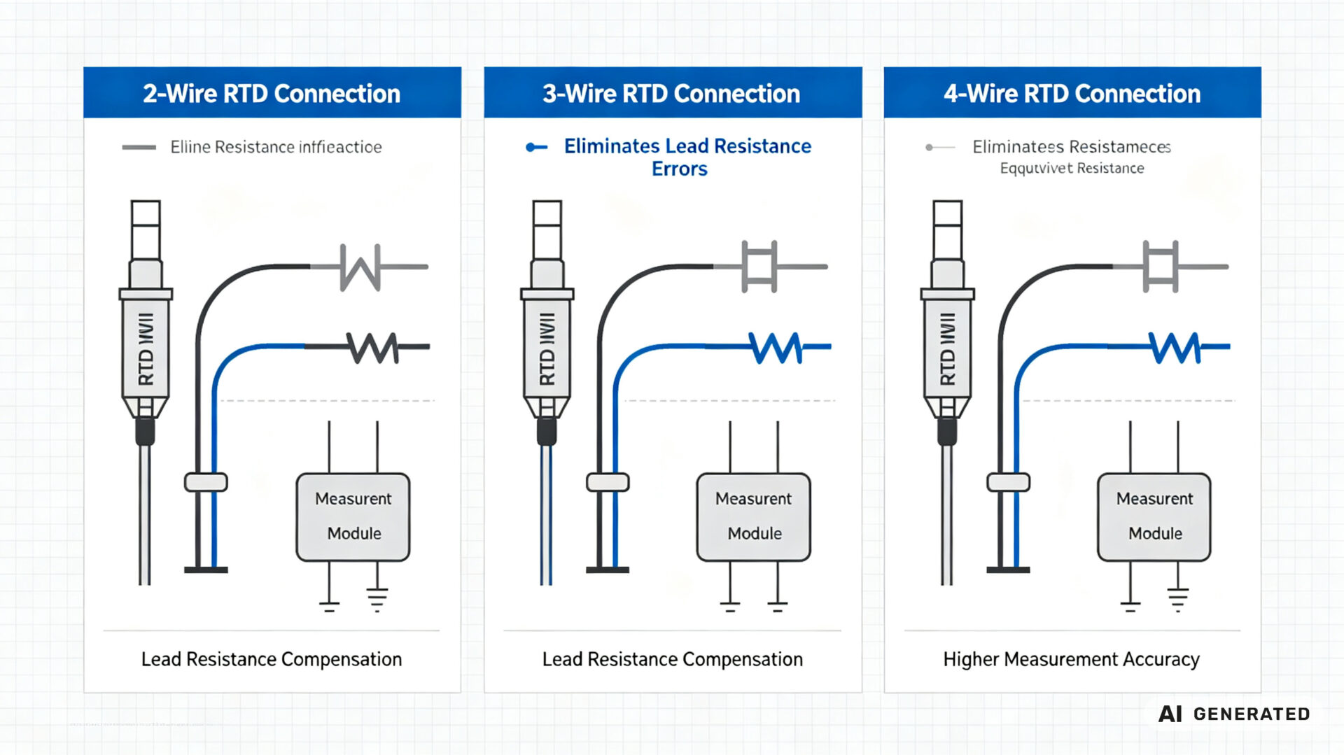
RTD sensors can connected in 2-wire, 3-wire, or 4-wire configurations, and the choice has a direct impact on measurement accuracy.
2-Wire Configuration: The simplest configuration uses two wires to connect the RTD to the measurement instrument. However, the lead wire resistance adds directly to the RTD resistance, creating an error that increases with cable length. For a 100 Ω Pt RTD, every 0.385 Ω of lead resistance represents a 1 °C error. 2-wire connections are generally not recommended for precision applications.
3-Wire Configuration: The 3-wire configuration is the industrial standard for most RTD applications. It uses three conductors: two for the current path and one for voltage sensing. By measuring the voltage drop across one current-carrying wire and assuming the other is identical, the instrument can compensate for lead resistance. A 3-wire setup provides accuracy close to a 4-wire setup and is widely used in industrial temperature transmitters from manufacturers including Endress+Hauser.
4-Wire Configuration: The 4-wire configuration provides the highest measurement accuracy by completely eliminating lead-wire resistance effects. Two wires carry the excitation current, and two separate wires sense the voltage across the RTD. Since the voltage-sensing wires carry negligible current, their resistance does not affect the measurement. 4-wire connections are typically used in laboratory and high-precision applications.
For RTD thermocouple cable assembly applications, TPS Elektronik provides cable assemblies configured for 2-wire, 3-wire, or 4-wire operation—with the appropriate conductor count, color coding, and termination to match the customer’s measurement instrument.
6. Materials Selection: Insulation, Jacket, and Temperature Rating
The materials used in a sensor cable assembly must match the application environment. Temperature extremes, chemical exposure, mechanical stress, and UV exposure all influence the choice of insulation and jacket materials.
Insulation Materials:
- PFA (Perfluoroalkoxy): Excellent high-temperature performance (up to 260°C), chemical resistance, and low dielectric constant. Suitable for demanding industrial and laboratory applications.
- PTFE (Polytetrafluoroethylene): Superior temperature resistance (up to 260°C) and chemical inertness, but more expensive and less flexible than PFA.
- PVC (Polyvinyl Chloride): Cost-effective for general-purpose applications up to 105°C, with good flexibility and abrasion resistance.
- LSZH (Low Smoke Zero Halogen): Required for applications where smoke and toxic fumes are a concern, such as in enclosed spaces.
Jacket Materials:
- Polyurethane (PUR): Excellent abrasion resistance and flexibility, suitable for moving cable applications
- PVC: General-purpose jacket with good durability and cost-effectiveness
- PFA/PTFE: High-temperature and chemical-resistant jackets for demanding environments
- Stainless steel overbraid: For mechanical protection in high-abrasion or high-temperature applications
Temperature Rating: The cable’s temperature range must match the application. IEC 60584-3 defines temperature ranges for thermocouple extension cables, typically from -25°C to +200°C. However, the usable range may be restricted by the insulation material.
TPS Elektronik provides sensor cable assembly services with a range of insulation and jacket materials to match application requirements—from general-purpose PVC to high-temperature PFA and mechanically rugged stainless steel overbraid.
7. TPS Sensor Cable Assembly Capabilities
TPS Elektronik’s sensor cable assembly service for RTD and thermocouple temperature sensors combines precision manufacturing, engineering support, and comprehensive quality assurance in a single integrated workflow.
Manufacturing Capabilities:
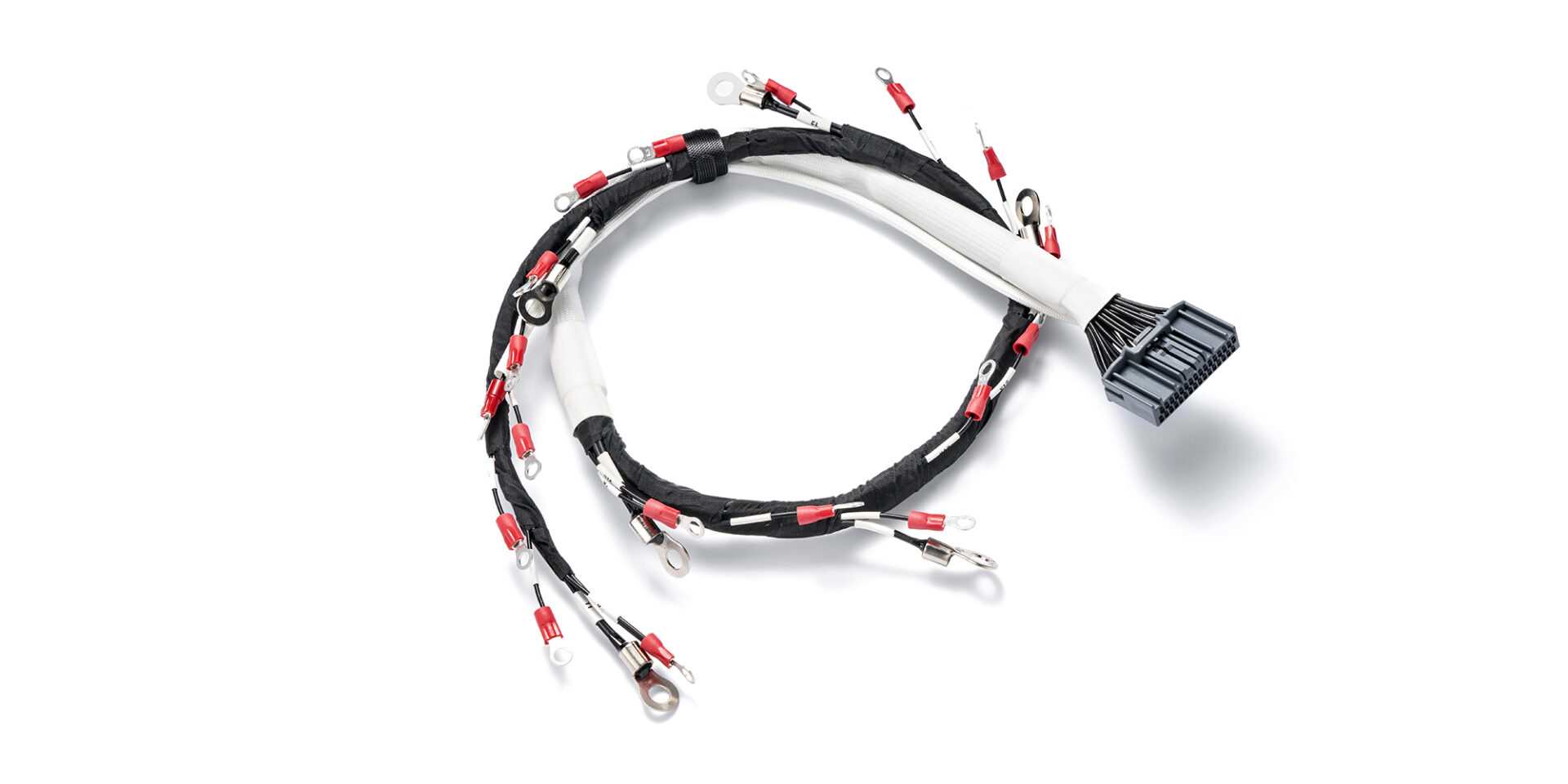
- Precision cutting and stripping: Automated cutting and stripping of shielded, twisted-pair sensor cables to exact lengths
- Crimping and soldering: Controlled crimping and soldering processes for reliable electrical connections to sensor connectors and terminals
- Shield termination: Proper shield termination with drain wires configured for single-point grounding
- Sensor-specific configurations: 2-wire, 3-wire, and 4-wire RTD connections; thermocouple extension cables with matching alloy types (KX, JX, TX, EX, NX)
- Connector options: M12, Lemo, thermocouple compensation plugs, and custom connectors
- Labeling and identification: Clear labeling for installation clarity and traceability
Engineering Support:
- DFM feedback: Design optimization for manufacturability and reliability
- Cable and connector selection: Guidance based on temperature range, chemical exposure, and mechanical requirements
- Color code compliance: IEC 60584-3 and ANSI MC96.1 color coding for thermocouple extension cables
- Length optimization: Balancing signal integrity and mechanical constraints
Quality and Testing:
- 100% continuity testing: Every conductor in every assembly verified for continuity and correct pin mapping
- Shielding effectiveness verification: Visual and electrical verification of shield termination integrity
- Insulation resistance testing: Verification of insulation integrity per applicable standards
- First Article Inspection (FAI): Comprehensive dimensional reports for the first part of each production run
- Documentation: Material certificates, test reports, and traceability documentation
TPS Elektronik’s sensor cable assembly service is part of a broader EMS workflow, integrating cable assembly with PCB assembly and system integration—reducing supply chain complexity for system integrators and procurement teams.