

System integrators, panel builders, and procurement teams in power electronics rarely fail because they lack a transformer design. They lose time—and margin—when leakage inductance in a small DC-DC transformer produces switch-node voltage spikes, ringing, and radiated emissions that only surface at full load or during EMC testing.
TPS Elektronik’s custom electromagnetic coils and winding goods built to reduce that risk: interleaved winding architectures. Which controlled inter-winding spacing, and measured leakage inductance from prototype through series production.
Discuss your low-leakage transformer requirements with TPS →
1. What leakage inductance means in a DC-DC transformer
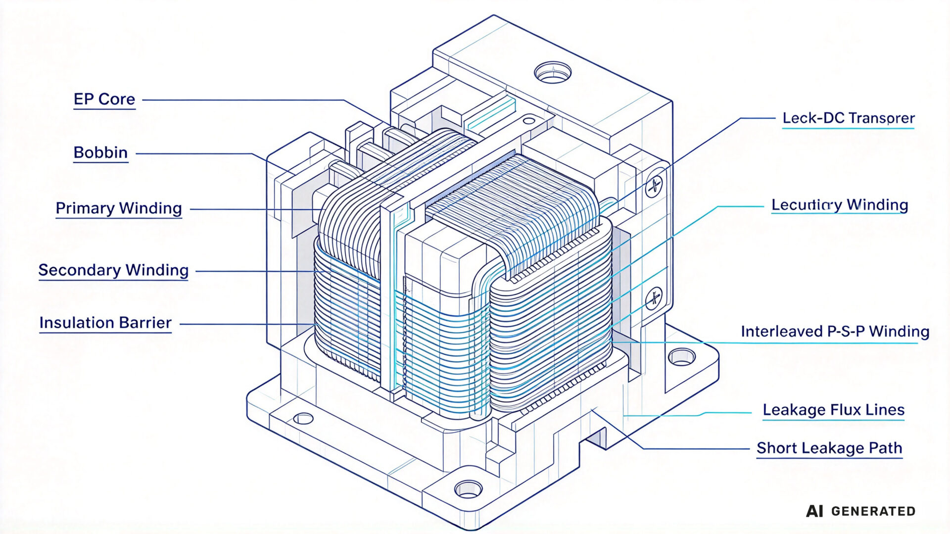
In an ideal transformer, all magnetic flux generated by the primary winding links the secondary winding. In a real transformer, a portion of the flux closes through the air, the bobbin, and the insulation between windings instead of linking both windings. The energy stored in this leakage field appears as a series inductance in the primary circuit—the leakage inductance.
For a DC-DC converter, leakage inductance is not a minor parasitic. It sets the switch-node voltage overshoot at turn-off, the ringing frequency after each switching transition, the duty-cycle loss in forward and flyback topologies. And the high-frequency content that must filtered to meet CISPR 11 or CISPR 32 limits. In a small power module, these effects dominate because the converter operates at high switching frequency and the transformer occupies a small fraction of the board area.
1.1 Where leakage flux comes from
Leakage flux generated wherever the magnetomotive force of the windings not perfectly balanced. Three factors dominate in small transformers: the physical separation between primary and secondary windings, the height of the winding window that not filled by copper, and the fringing flux around the core gap in gapped designs.
The separation term is the most controllable. Every millimetre of insulation, creepage distance, and bobbin wall between primary and secondary adds a path for leakage flux. Safety standards such as IEC 61558-1 define minimum insulation distances, so the design task is to meet those distances while minimising the winding separation that is not required for safety.
1.2 Why small power modules are more sensitive
Leakage inductance scales with the winding geometry, but it does not scale down as fast as the transformer’s magnetising inductance. In a small module, the number of turns is low, the winding window is small, and the insulation thickness becomes a large fraction of the total winding build. The result is a leakage inductance that can reach 5–15% of the magnetising inductance—enough to produce a switch-node overshoot of tens of volts at a few amperes of load current.
At the same time, the switching frequency in small modules is high, so the current commutation rate di/dt is large. The voltage spike produced by the leakage inductance is V = Lk × di/dt, which means a leakage inductance that would be acceptable at 100 kHz becomes a problem at 500 kHz.
2. Winding architectures that reduce leakage inductance
Reducing leakage inductance is a winding geometry problem before it is a component selection problem. The objective is to maximise the magnetic coupling between primary and secondary while maintaining the insulation distances required by the applicable safety standard and the manufacturability required for series production.
2.1 Interleaved and sandwich windings
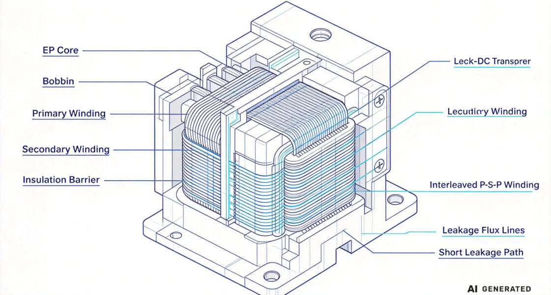
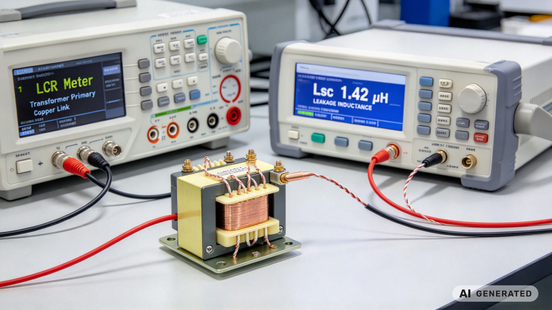
The most effective single measure to split the primary winding into two halves and place the secondary between them—the classic P-S-P sandwich. Each half-primary is closer to the secondary, so the leakage flux path is shortened and the stored leakage energy falls. In small transformers, a well-executed sandwich can reduce leakage inductance by 40–70% compared with a conventional primary-then-secondary arrangement.
Further interleaving, such as P-S-P-S or multiple parallel secondary layers, reduces leakage inductance further but increases winding complexity and inter-winding capacitance. The optimum depends on the converter topology, the switching frequency, and the acceptable common-mode noise level.
2.2 Core, bobbin, and conductor geometry
The core shape determines how much of the winding window is available for copper. Pot cores, RM cores, EP cores, and planar ER cores concentrate the winding around the centre leg and reduce the mean length per turn, which lowers both copper loss and leakage inductance. Planar windings on a multilayer PCB offer very tight coupling and repeatable geometry, which is why they are common in small power modules above 200 kHz.
The conductor also matters. Foil windings for high-current secondary turns maximise the copper fill of the window and reduce the distance between the primary and secondary current sheets. Litz wire reduces skin and proximity effect losses, but it does not by itself reduce leakage inductance—it must combined with an interleaved layout to have an effect.
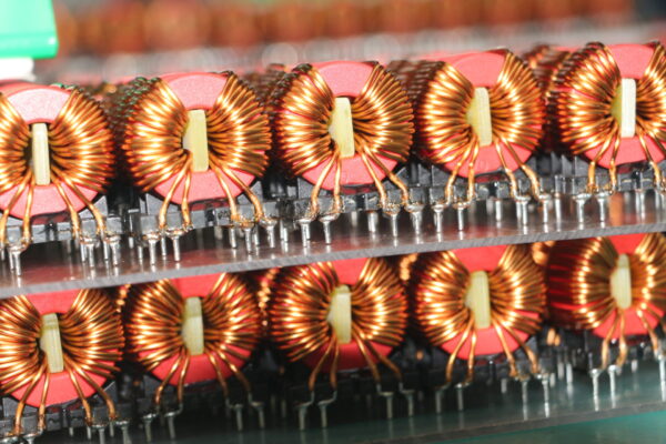
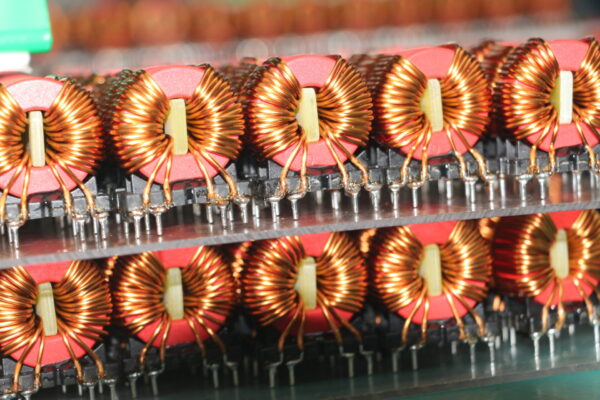
For designs where a toroidal geometry is preferred, the distributed winding gives inherently low leakage. But the winding cost and repeatability must evaluated against the application. TPS’s toroidal coils and production-ready transformer resource covers this trade-off in more detail.
2.3 The trade-off with winding capacitance
Every reduction in leakage inductance through closer coupling increases the inter-winding capacitance. That capacitance provides a path for common-mode currents to flow from the primary side to the secondary side. Which can increase conducted emissions at the switching frequency and its harmonics. The design target is therefore not “minimum leakage inductance” but a balanced set of leakage inductance, inter-winding capacitance, and insulation distance that meets the converter’s electrical and EMC requirements.
This is why TPS treats the transformer as part of the converter design rather than as a stand-alone part. The wire insulation materials guide documents the insulation options that affect both the safety distance and the winding build.
3. How TPS custom electromagnetic coils deliver low leakage in production
TPS Elektronik produces custom electromagnetic coils and wound components as part of its EMS portfolio, including high-frequency transformers, toroidal coils, and DV/DT chokes. For small DC-DC power modules, the workflow built around three stages: design review, measurement, and series transfer.
3.1 Design-for-winding review
The review starts with the converter requirements: input and output voltage, switching frequency, target leakage inductance, isolation class, and the available footprint. TPS engineers then evaluate the winding arrangement, the core and bobbin choice, the conductor type. And the interleaving scheme against the manufacturability constraints of the winding machine.
The output is a winding specification that defines the layer order, the number of turns per layer, the insulation between layers, the termination method, and the target leakage inductance with a tolerance band. For medical and high-frequency applications, the medical high-frequency transformer and coil winding resource describes the additional documentation and process controls that apply.
3.2 Measurement and validation
Leakage inductance measured with the secondary winding shorted and an LCR meter or impedance analyser connected to the primary. The measurement must made at the converter’s switching frequency, not at 1 kHz, because the leakage inductance is frequency-dependent due to skin and proximity effects in the windings. TPS measures at the application frequency and records the result on the winding datasheet.
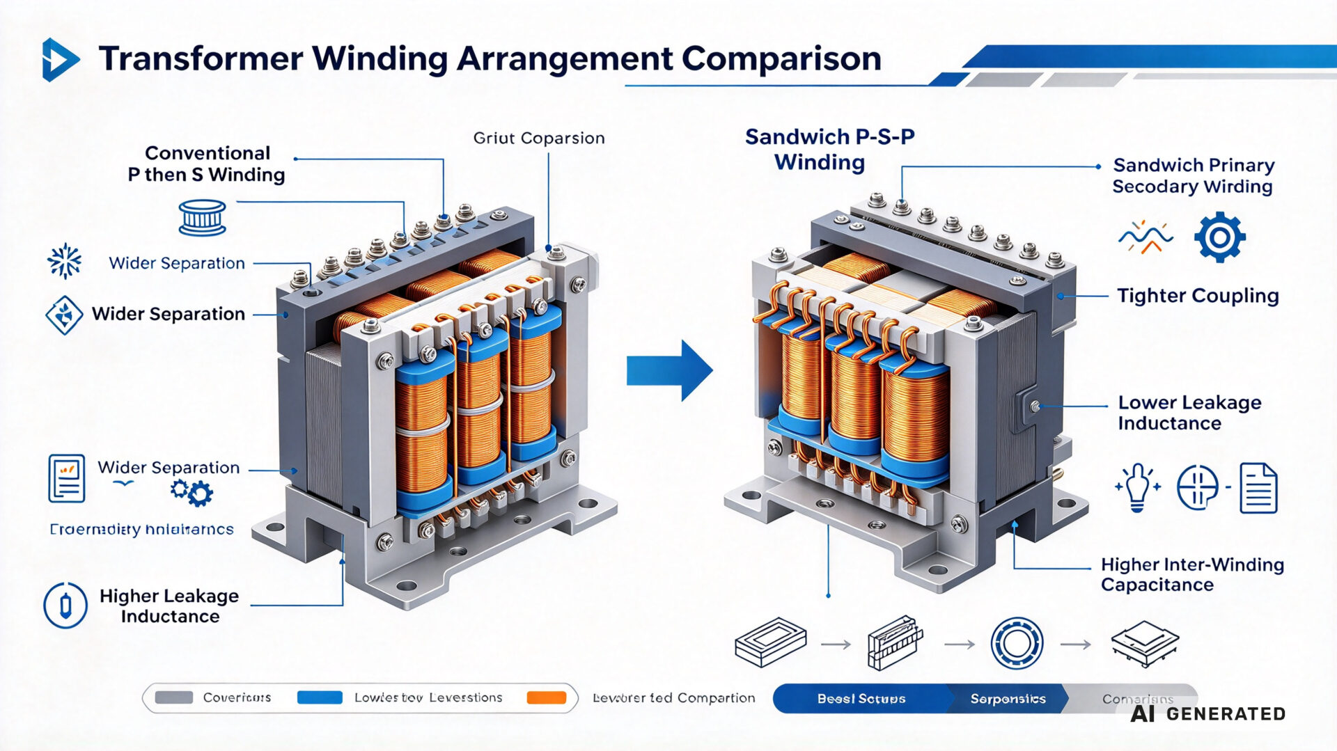
The validation set also includes turns ratio, magnetising inductance, inter-winding capacitance, hipot withstand voltage, and insulation resistance. For high-frequency designs, the winding loss evaluated with a impedance analyser sweep to confirm that the AC resistance stays within the thermal budget.
3.3 From prototype to series
Once the prototype winding meets the electrical and thermal targets, TPS transfers the design to programmable winding machines with tension control, turns counting, and layer insulation placement. The critical parameters for repeatability are wire tension, winding speed. And the position of the interleaving layers—all of which controlled by the machine program and verified by first-article inspection.
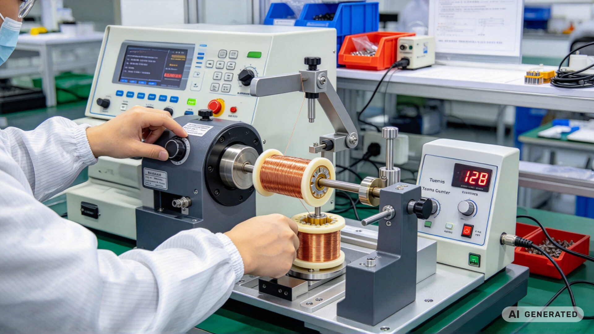
Series production includes 100% hipot and turns-ratio testing, with leakage inductance measured on a sample basis or on every unit for critical applications. The coil winding service page describes the production scope, and the Helmholtz coil guide provides background on the magnetic field principles that underlie the winding design.
4. RFQ checklist for low-leakage DC-DC transformers
To streamline quotation and evaluation, provide the following information when requesting a low leakage transformer for a small power module:
- Electrical specification: Input and output voltage, output power, switching frequency, and topology (flyback, forward, push-pull, LLC)
- Leakage inductance target: Nominal value, tolerance, and measurement frequency and conditions
- Magnetising inductance and turns ratio: With tolerance bands
- Isolation requirements: Working voltage, isolation class, hipot voltage, and the applicable safety standard (for example IEC 61558-1)
- Mechanical constraints: Maximum footprint, height, mounting method, and termination type
- Thermal requirements: Ambient temperature, allowable temperature rise, and cooling method
- Production volume: Prototype quantity, annual volume, and expected lifetime
- Documentation: Winding datasheet, first-article inspection report, hipot test record, and material declarations
Providing these details reduces clarification cycles. TPS’s engineering team can support the winding architecture selection and the leakage inductance target definition as part of the RFQ process.