TPS Elektronik positions the AC Inrush Current Limiter as a practical BoFu component for exactly that cabinet-level problem: controlled startup on DIN rail, integrated bypass relay instead of a simple NTC-only approach, and current classes that fit real industrial panel design workflows.
1. Why AC Inrush Current Limiting Affects RFQ Outcomes
In many industrial cabinets, the steady-state current is not the real approval problem. The real problem is the first 100 milliseconds after power-on.
That is where bulk capacitors charge, transformer magnetization peaks, and several downstream devices demand line current at the same time. On paper, the branch may look acceptable. In commissioning, however, the result can be nuisance tripping, conservative over-dimensioning of protection, or field delays that erode confidence in the whole build.
For system integrators and panel builders, that directly affects RFQ quality because startup risk changes more than the electrical BOM. It changes:
- branch protection strategy,
- cabinet wiring assumptions,
- device grouping on one feeder,
- commissioning predictability, and
- serviceability after power cycling.
Procurement sees the same issue from a different angle. If startup behavior is not stabilized, teams often compensate by buying larger breakers, adding design margin everywhere, or splitting branches that otherwise could have remained simpler. That increases cost, footprint, and approval effort.
The value of an AC Inrush Current Limiter is therefore not theoretical. It is very practical: it helps keep startup current under control so that the cabinet behaves more like the design review promised.
That is especially relevant when the limiter sits ahead of DIN-rail supplies such as the TPS010-100W GP Series, the TPS030-130W Pro Series, or higher-boost DIN-rail platforms like the TPS100-320W Peak DR Plus, where several loads may energize together.
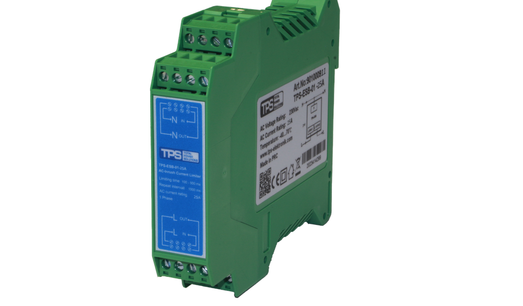
2. TPS Series Overview: DIN-Rail Startup Control for 230VAC and 400VAC Environments
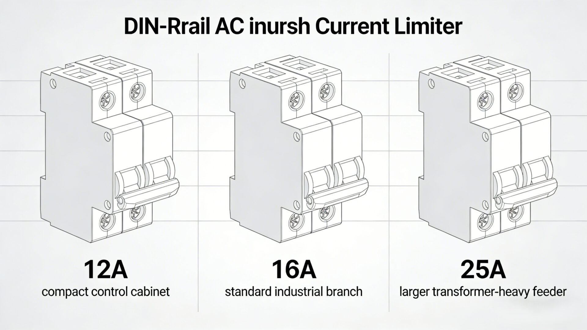
The TPS AC Inrush Current Limiter family is built for DIN-rail installation and covers the current classes most often discussed in industrial control power entry design: 12A, 16A, and 25A.
From a BoFu perspective, this matters because buyers and designers are not looking for “any limiter.” They are looking for a limiter that fits the cabinet architecture already in progress. The TPS family does that by aligning with panel-friendly form factors, screw terminal wiring, convection cooling, and industrial operating conditions.
For single-phase branches, the shop-linked models are:
Within the broader family context, the datasheet also identifies 400VAC three-phase order variants, which is useful for engineering teams that want one design language across cabinet types rather than one-off component logic per project.
Key technical characteristics that shape selection include:
- DIN-Rail Mount for cabinet integration,
- integrated bypass relay,
- peak current limiting to 45A,
- limiting time of 100–500ms,
- IP20 protection,
- convection cooling,
- -40°C to 70°C operating temperature, and
- 300,000h MTBF.
That combination makes the device easier to discuss in actual RFQs because it connects electrical function, enclosure integration, and procurement language in one component line instead of scattering those topics across several workaround parts.
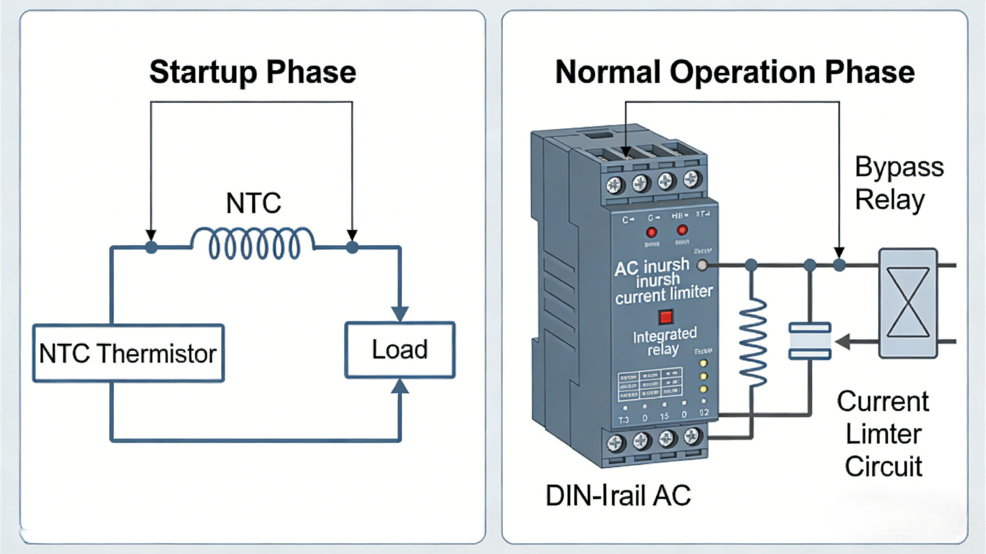
3. Why an Integrated Bypass Relay Matters More Than a Simple NTC Solution
One of the strongest differentiators in this product family is the integrated bypass relay. That detail deserves attention because many teams first think about inrush limitation through the lens of a basic NTC solution.
An NTC can be useful in simple scenarios, but in industrial cabinets it often raises questions that system integrators do not want to keep answering during FAT, SAT, or later service calls. NTC behavior depends on temperature history. After recent operation, the device may still be warm, which changes how it behaves during the next startup. In repeated cycling environments, that can reduce predictability.
With a bypass relay architecture, the limiter can perform the startup-limiting function and then transition out of the main current path after the inrush event. In practice, that supports a more stable design discussion around:
- repeated switching,
- reduced thermal stress during normal running,
- more consistent startup behavior, and
- a more engineering-oriented alternative to “just add an NTC and hope the branch tolerates it.”
That does not mean every cabinet must use a relay-based limiter. It means that for higher-value industrial systems, relay-assisted startup control is often easier to justify because it reduces operational ambiguity. That is exactly the kind of argument that helps both engineering and purchasing converge on one approved part instead of reopening the discussion at every design review.
If your project involves multiple AC/DC platforms on one feeder, that startup discipline can be especially useful ahead of compact DIN-rail power supplies like the TPS010-100W GP Series or more performance-oriented models such as the TPS030-130W Pro Series.
4. Where the TPS Limiter Fits in Real Cabinets: Capacitive, Inductive, and Transformer-Heavy Loads
The datasheet positions this limiter for inductive loads, capacitive loads, and isolating transformers. That is important because those categories map directly to common industrial cabinet pain points.
4.1 Capacitive loads
Many power electronics products present heavy input capacitance at switch-on. That includes DIN-rail supplies, IPC power supplies, industrial ATX units, and open-frame platforms. When several such devices are grouped on one branch, the startup pulse can be disproportionate to normal running current.
Typical examples in TPS-related system contexts include the FSP300-70PFL-SK, FSP700-80PSA-SK, FSP500-50FDB, or the TPS-GSH180S open-frame supply.
4.2 Inductive loads
Inductive branches create a different startup challenge. Magnetizing current, switching state, and branch topology can combine in ways that look harmless in nominal calculations but still upset protective devices during energization.
4.3 Isolating transformers
Transformer-fed subassemblies are classic inrush candidates. In these systems, a limiter is not just a comfort feature. It can be part of making the branch behave in a repeatable way when the machine is powered on after installation, maintenance, or an unplanned stop.
Another useful point from the TPS application framing is that the limiter can support smaller and faster circuit breaker strategies and may help with reduction of cabling sections where the overall branch concept supports it. In practice, that does not remove the need for proper protection coordination. It does, however, help engineering teams argue for a more optimized cabinet instead of a blanket “make everything bigger” approach.
For procurement, that is a conversion point: if one DIN-rail limiter stabilizes startup behavior, the discussion can move from corrective action to planned configuration.
5. How to Choose 12A, 16A, or 25A
For BoFu buyers, model selection needs to stay simple. The cleanest way to evaluate the family is to start from the continuous branch current, then look at load composition, then confirm available input environment.
5.1 When 12A makes sense
The TPS-ESB-01-12A is a strong fit for compact single-phase branches with moderate nominal current but meaningful startup peaks, such as grouped DIN-rail supplies, smaller control cabinets, compact IPC branches, or transformer-assisted auxiliary circuits.
5.2 When 16A is the practical middle ground
The TPS-ESB-01-16A is the most natural evaluation point for many industrial RFQs because it sits where a lot of real panel designs land: not minimal, not oversized, but flexible enough for broader feeder strategies and future branch growth.
5.3 When 25A is the safer choice
The TPS-ESB-01-25A is typically the better candidate when the branch aggregates larger capacitive loads, more substantial transformer behavior, or a higher planned device count on one input segment.
In selection discussions, do not choose only by nominal nameplate current. Also ask:
- How many downstream devices start at once?
- Are there large bulk capacitors on the input side?
- Is transformer magnetization part of startup behavior?
- How aggressively do you want to coordinate upstream breakers and fuses?
- Will the cabinet be power-cycled frequently?
Those questions move the decision from generic current matching to actual RFQ suitability.
6. Installation, Protection, and Panel Design Notes
The product is designed for DIN-rail mounting and supports mounting at DIN rail TS 35/7.5 or TS 35/15 vertical. For panel builders, that matters because startup-control components only help when they fit neatly into the cabinet build sequence rather than forcing awkward mechanical compromises.
The family uses screw terminals in the AWG13-11 range and relies on convection cooling, which keeps the installation concept straightforward for standard enclosures. The datasheet dimensions also support practical cabinet planning: approximately 22.5 mm width, 100 mm height, and 112 mm depth. That slim format is useful when the device must sit close to feeder protection or next to grouped power-conversion hardware.
Protection conversations should stay realistic. An inrush current limiter does not replace proper fuse or breaker design. It improves the branch’s behavior so that protection coordination can be done with fewer startup surprises. That is why the datasheet application language around unintended fuse release and support for smaller, faster circuit breakers is commercially important: it speaks directly to control-cabinet optimization.
Two practical design notes are worth keeping in the RFQ package:
- The limiter should be selected as part of the branch architecture, not as a late corrective accessory.
- Downstream device grouping should be documented clearly, especially if several supplies or transformer-fed subcircuits energize together.
That is also where internal cross-checking against the actual downstream hardware helps. If the branch feeds DIN-rail platforms such as the TPS100-320W Peak DR Plus or IPC-oriented supplies like the FSP350-70PFL-SK, the startup grouping should be described explicitly.
7. Compliance, Reliability, and Procurement-Facing Documentation
For engineering and procurement alignment, the product’s documentation profile matters almost as much as the startup function itself.
The limiter family is specified with IP20 protection, 50 Hz input context, humidity up to 95% RH non-condensing, altitude up to 2000 m, and a storage temperature range down to -40°C. The documented safety and EMC references include EN60950-1, EN61000-6-2, EN61000-6-3, CE, and RoHS. In B2B buying processes, those data points help reduce back-and-forth during supplier review.
The listed 300,000h MTBF is also relevant in panel programs where reliability messaging has to pass through both engineering review and purchasing approval.
For broader process and standards background, many teams also map component qualification and supplier documentation against official references such as ISO quality management, IEC standards background, and the European Commission CE marking overview.

8. What to Include in Your RFQ
A high-conversion RFQ for an AC Inrush Current Limiter should not stop at “need a 16A unit.” It should describe how the branch behaves.
Recommended RFQ inputs include:
- single-phase 230VAC or broader family reference including 400VAC cabinet context,
- rated branch current target: 12A, 16A, or 25A,
- downstream load type: capacitive, inductive, transformer-based, or mixed,
- number of downstream power supplies or transformers switching simultaneously,
- upstream fuse or circuit breaker concept,
- ambient temperature and cabinet ventilation assumptions,
- space constraints on DIN rail, and
- whether frequent power cycling is expected.
That information lets TPS or your internal engineering team evaluate the limiter as part of the full startup chain instead of as an isolated catalog item.
For buyers who already know the current class, the fastest path is usually direct model evaluation:
That keeps the conversation where it should be: on startup control, branch protection, and RFQ certainty.
FAQ
What is an AC inrush current limiter used for?
It is used to control the short startup current peak that appears when capacitors charge, transformers magnetize, or several AC-powered devices energize at once. In panel applications, that helps reduce nuisance tripping and improves branch startup predictability.
Why not just use a simple NTC?
A simple NTC may be sufficient in some basic designs, but industrial cabinets often need more predictable behavior across repeated switching and different thermal states. A limiter with an integrated bypass relay is usually easier to justify in higher-value systems.
How do I choose 12A, 16A, or 25A?
Start with the branch’s continuous current, then check the downstream load mix, simultaneous startup behavior, transformer presence, and breaker coordination target. Do not size the device by nameplate current alone.
Can it help with breaker and fuse coordination?
Yes, that is one of the main reasons to specify it. By limiting startup peaks, the branch can often be coordinated more cleanly with upstream protective devices. Final protection design still needs to be validated at the system level.
Which applications fit best?
It is especially relevant for inductive loads, capacitive loads, isolating transformers, grouped DIN-rail power supplies, industrial IPC power branches, and other cabinet feeders where startup current is high compared with normal operating current.


