Key Takeaways
- Inrush current (also called startup current) can significantly exceed steady-state current and may affect protective devices and components.
- NTC thermistor-based limiters are simple but can introduce cool-down delays and continuous power dissipation.
- Designs with integrated bypass relays reduce steady-state losses and improve restart behavior.
- DIN rail (TS35) modules provide a structured integration approach for industrial panels and distribution systems.
- Proper selection depends on load type, current rating, switching behavior, and environmental conditions.
1. Understanding Inrush Current
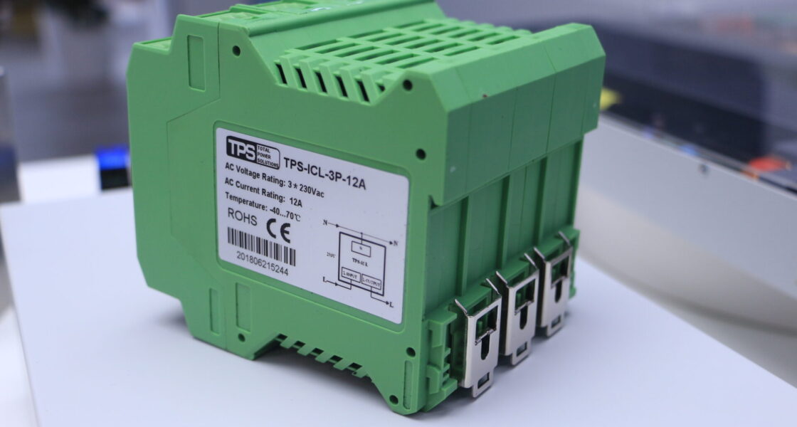
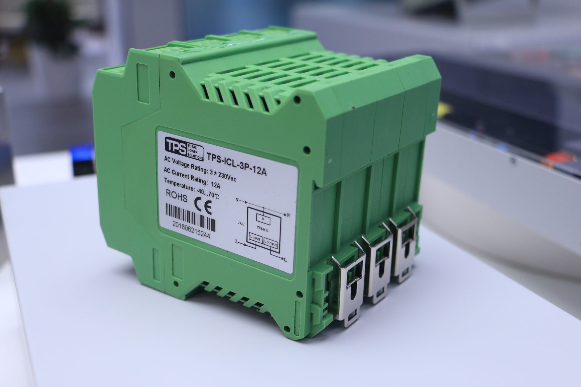
Discover the TPS-ICL-3P inrush current limiter series for 3-phase 400 V AC inputs, available in 12 A and 25 A versions for PV inverters and industrial control cabinets.
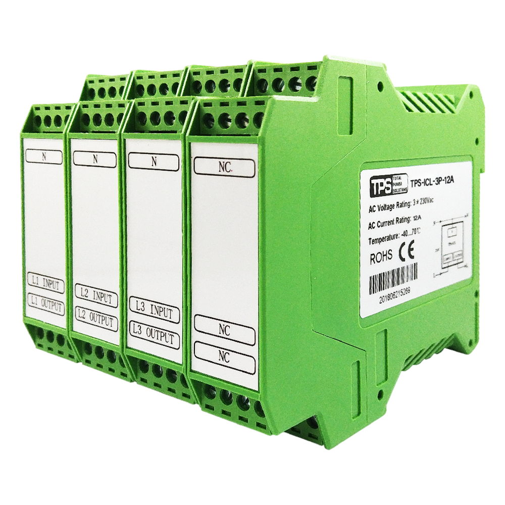
TPS-ICL-3P-12A
3-phase inrush current limiter, 12 A. Ideal for small 3-phase PV inverters and compact industrial control panels.
View product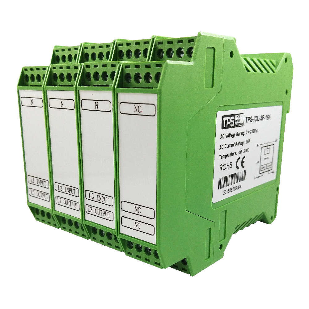
TPS-ICL-3P-16A
3-phase inrush current limiter, 16 A. Ideal for protecting motors, transformers, and other three-phase inductive/capacitive loads from damaging inrush currents.
View product
TPS-ICL-3P-25A
3-phase inrush current limiter, 25 A. Designed for 10–30 kW PV inverters and demanding industrial applications.
View productInrush current is the initial high current drawn when electrical equipment is energized. It typically occurs because the load presents a low impedance at startup.
Common examples:
- Capacitors initially behave like short circuits
- Transformers may experience core saturation
- Motors have no back electromotive force (back EMF) at standstill
As a result, current peaks may occur for microseconds up to several hundred milliseconds.
1.1 Physical Background
The magnitude of inrush current depends on:
- The switching point of the AC waveform
- Residual magnetism in inductive components
- Total circuit impedance
For capacitive loads, the relationship can be approximated by:
I = C · dV/dt
This explains why fast voltage changes can lead to high current peaks.
2. Effects of Uncontrolled Inrush Current
Uncontrolled inrush current may lead to:
- Nuisance tripping of circuit breakers
- Fuse operation during startup
- Increased stress on rectifiers and capacitors
- Contact wear in relays and contactors
In addition, voltage dips may affect other connected equipment.
For these reasons, inrush current limiting is often considered during system design, particularly in industrial environments.
3. Technologies for Inrush Current Limiting
Different technologies are available depending on application requirements.
3.1 NTC Thermistors
NTC (Negative Temperature Coefficient) thermistors are widely used.
Operating principle:
- High resistance when cold → limits initial current
- Resistance decreases as temperature rises → allows normal operation
Advantages:
- Simple implementation
- Passive component
- Cost-effective
Limitations:
- Requires cool-down before next startup
- Continuous power dissipation during operation
3.2 Limiters with Bypass Relay
To address these limitations, some designs include a bypass relay.
Typical operation:
- At startup, current flows through a limiting element
- After a short delay, a relay bypasses the element
- During steady operation, current flows through a low-resistance path
Benefits:
- Reduced steady-state power loss
- Improved restart capability
This approach is often used where frequent switching or energy efficiency is relevant.
3.3 Fault Current Limiting
Fault current limiters are designed to respond to abnormal conditions such as short circuits.
Examples include:
- Solid-state limiters in power electronics systems
- Specialized solutions in utility networks
For many industrial applications, a dedicated inrush current limiter is sufficient.
3.4 Symbols and Schematics
Typical schematic representations include:
Relay bypass designs: thermistor with parallel contact
NTC thermistor: resistor with temperature marking
Active limiter: functional block or current control symbol

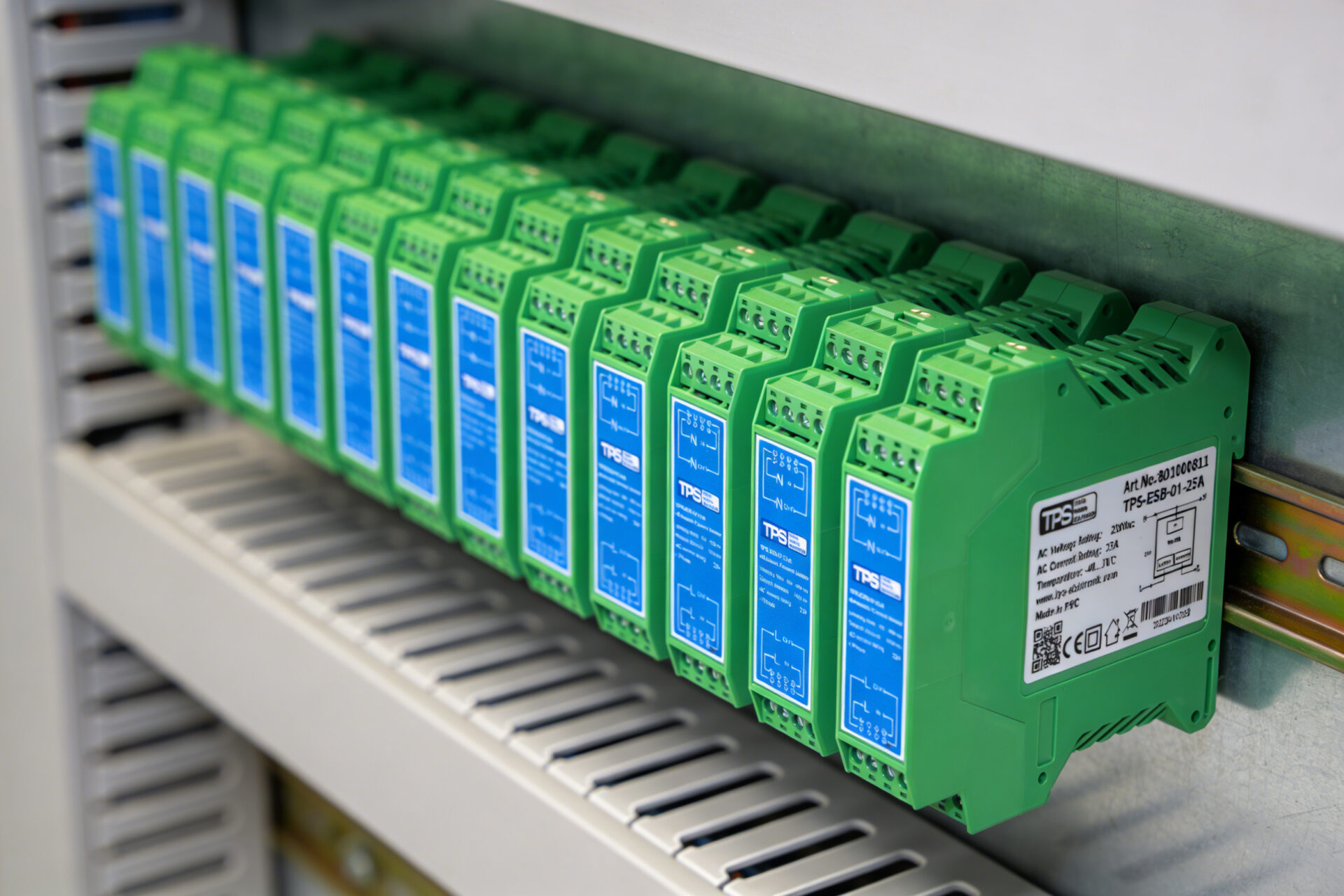
4. DIN Rail Mounted Inrush Current Limiters
DIN rail (TS35) modules provide a modular installation approach in control panels and distribution systems.
Typical characteristics:
- Mounting on standard 35 mm DIN rail
- Compact housing design
- Screw terminal connections
- Integration into existing panel layouts
Practical advantages:
- Simplified installation
- Scalable system design
- Structured wiring layout
Most modules are intended for installation inside enclosures with IP20 protection and natural convection cooling.
5. Key Performance Parameters
When selecting a limiter, several parameters should be evaluated.
5.1 Peak Current Limiting
Defines the maximum inrush current allowed for a defined duration.
Typical values depend on the device and application.
5.2 Repeat Interval
Indicates how quickly the device can handle a new startup event.
- NTC-only solutions: longer recovery time
- Relay-based solutions: shorter intervals possible
5.3 Environmental Conditions
Check:
- Operating temperature range
- Humidity limits
- Installation altitude
5.4 Compliance and Standards
Depending on application, relevant standards may include:
- EN 62368-1
- EN 61000 series (EMC)
Compliance depends on the specific product and manufacturer documentation.
6. Typical Application Areas
6.1 Industrial Equipment
Motors, conveyors, compressors
6.2 HVAC Systems
Compressors and control electronics
6.3 Lighting Systems
LED drivers and electronic ballasts
6.4 UPS Systems
Controlled restart of downstream loads
6.5 Variable Frequency Drives (VFDs)
DC-link capacitor charging
6.6 Power Distribution
Centralized protection in panels and infrastructure
7. Selection Guidelines
7.1 Define Electrical Parameters
- Steady-state current (RMS)
- Expected inrush peak
- Supply voltage and frequency
7.2 Consider Load Type
- Capacitive
- Inductive
- Mixed loads
7.3 Evaluate Operating Conditions
- Temperature
- Switching frequency
- Installation space
7.4 Choose Suitable Technology
- NTC → simple, low-cost
- Relay-based → improved efficiency and restart behavior
8. Installation Guidelines
- Disconnect power before installation
- Use appropriate tools and insulation
- Ensure correct mounting orientation
- Provide adequate ventilation
- Follow specified wire sizes and torque values
DIN rail modules are typically intended for indoor use within enclosures.
9. FAQ
Q: Is inrush current the same as startup current?
Yes, both terms are used interchangeably.
Q: Can NTC thermistors be used alone?
Yes, depending on switching frequency and thermal conditions.
Q: Are DIN rail limiters suitable for three-phase systems?
Use dedicated three-phase versions where required.
Q: What is a wide-range limiter?
A device designed for broader input voltage ranges (e.g., global applications).
10. Outlook
Advances in power electronics (e.g., wide bandgap semiconductors and digital control) are influencing current limiting concepts. However, established solutions such as relay-based limiters and passive components remain widely used in industrial applications.
11. Conclusion
Inrush current is a common effect in electrical systems. With appropriate design and component selection, its impact can be managed effectively.
Selecting a suitable inrush current limiter involves:
- Understanding the load behavior
- Matching electrical parameters
- Considering environmental and operational conditions
Consult manufacturer documentation to ensure correct application and compliance.


