Last winter, a maintenance technician on a remote Norwegian fish farm opened a control cabinet to find three of six power supplies dead. The ambient temperature had touched -18°C overnight. Salt-laden air and thermal cycling had corroded connectors and cracked solder joints. The units were generic industrial power supplies, properly specified on paper, but never designed with a genuine understanding of cumulative stress. That story is not unusual. It repeats across European wind farms, Alpine water treatment plants, and automotive pressing lines. The common thread is rarely a missing certification. It is the absence of a systematic engineering approach. This approach must treat a din rail power supply as a critical node within a harsh physical environment, not a standalone component.
Our own journey toward a self-manufactured range of dc power supplies began with that recognition. The European market does not need yet another 24 volt power supply with a familiar housing and a datasheet copied from an ODM catalogue. It needs an industrial power supply platform engineered from the silicon up. The platform must handle wide-input surges, thermal shock, continuous vibration, and altitude extremes without hidden derating. In this article, we open up the design methodology that underpins our upcoming ac-dc power supply generation. We share the engineering decisions that transform components into a stabilised power supply. You can install it on a DIN Rail TS 35/7.5 or TS 35/15 and forget it for a decade.
Starting Where the Datasheet Usually Stops: The Real Input Environment
Most ac to dc power supply specifications quote a universal input of 90 to 264 VAC. That sounds comprehensive. Yet industrial mains in rural Bavaria or a Portuguese solar farm can sag below 90 VAC during motor starts. DC bus systems in material handling often operate from a 120-370VDC power supply rail. This rail fluctuates with battery state-of-charge. A power supply that loses regulation or damages its input capacitors under these conditions will cause nuisance trips. Those trips erode trust faster than any specification sheet can restore.
We designed the input stage to manage exactly these transients. We size the bulk capacitor bank for more than just a 20ms hold up time at full load and 230 VAC. It maintains output stability for 10 ms at 100 VAC, the low end of the 90-264VAC power supply range. An active inrush limiter uses a low-resistance MOSFET, not an NTC thermistor. This ensures cold-start inrush currents stay below 30 A during rapid cycling. For installations on a 120-370VDC power supply bus, we added a dedicated DC detection circuit. It bypasses the rectifier losses, improving efficiency by up to two percentage points and reducing internal heat. These are not catalogue options. They are circuit-level decisions we make because we own the complete electrical design.
- Active inrush limiter keeps cold-start currents predictable and protects upstream MCBs.
- Bulk capacitor sizing provides true 20 ms ride-through at 230 VAC and stable operation at 100 VAC.
- DC input path bypasses rectifier for improved efficiency when supplied from a 120-370VDC power supply rail.
Why We Refuse to Put a Fan Inside: The Convection Cooled Commitment
A fan turns reliable electronics into a maintenance item. In a sealed building automation power panel, a seized fan bearing pushes temperatures past capacitor ratings. This cuts the effective lifetime from fifteen years to three. Even before failure, fans draw in dust, fibres, and corrosive gases. This is especially damaging in wastewater treatment or coastal installations. Our design mandate was simple: no fans, no moving parts, full power at 50 °C ambient. Pure convection cooling.
Achieving True Convection Cooled Performance
To hit useful power densities, we rethought the mechanical architecture. We designed the aluminium housing as an active thermal element, not a cosmetic wrapper. We ran iterative CFD simulations to shape the fin geometry and internal air gaps. When mounted vertically on a standard DIN rail, the chimney effect pulls cool air across the transformer and output diodes.
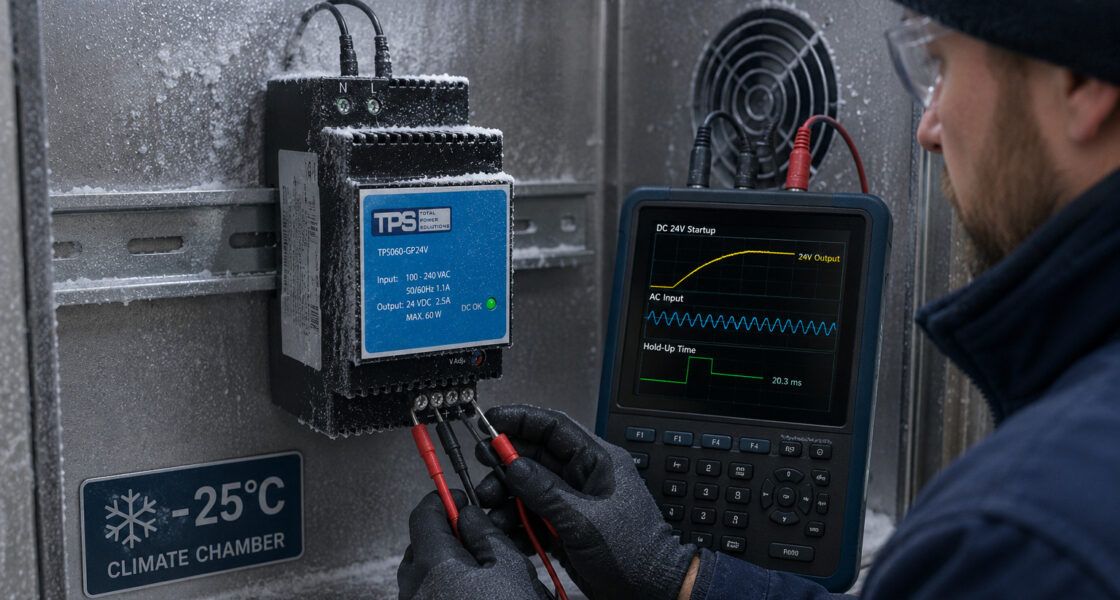
We tested every prototype in a calibrated environmental chamber at 0 to 50℃ power supply extremes. The result: no derating up to 50 °C and a cold start at -25 °C without pre-heating. For high-altitude sites like Swiss lift stations, the same margins guarantee full performance as a 3000m altitude power supply. Thin air reduces cooling and dielectric strength, but we design for the worst-case combination of 50 °C and 3000 m. A typical European installation therefore operates with enormous thermal headroom.
- Fanless, fully sealed aluminium housing acts as both EMI shield and convection-cooled heatsink.
- Full load rating maintained from 0 °C to 50 °C, with reliable -25 °C cold starts.
- Designed and tested for 3000 m altitude without derating, to cover all practical European installations.
Designing for the Vibrating World: From Modal Analysis to Staking Compound
Vibration is the silent killer of power electronics. A 12v power supply on a printing press or stone crusher endures continuous excitation. This can fracture component leads, fret connectors, and crystallise solder joints. Some engineers specify a higher-rated unit and hope for the best. We took a more deterministic path.
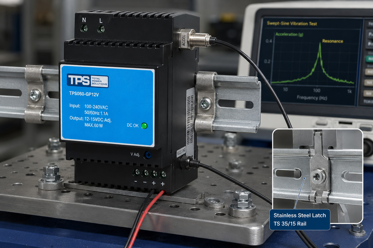
Before cutting the first PCB, we built a finite-element model of the entire assembly. It included the housing, PCB, heavy magnetics, and the DIN rail latch. We aimed to push the first resonant frequency well above 120 Hz. This sits above the excitation band of most rotating machinery and far from mains-related vibrations. We added adhesive staking to components over 5 grams, like transformers and large capacitors. This shifted their local modes. Six snap-fit pillars support the PCB. They prevent the board from acting as a large membrane that would amplify strain on surface-mount components.
We also focused on the rail interface, the single mechanical connection to the cabinet. Our stainless steel latch maintains constant spring force after thousands of thermal cycles. We verified the design on an electrodynamic shaker. We ran random vibration profiles per IEC 60068-2-64 and monitored earth continuity and output regulation. The latch, combined with TS 35/7.5 and TS 35/15 compatibility, keeps the unit connected. It powers a safety system power supply in a rail signalling cabinet or an alarm system power supply in a seismic bracing frame without interruption.
Embedding Protections That Do Not Wait for a Microcontroller
A stabilised power supply that waits for a microprocessor to protect itself is fragile. Firmware can hang. Brown-out conditions leave a microcontroller in an undefined state. The boot sequence can take hundreds of milliseconds. For immediate threats like overvoltage and overtemperature, we chose hardware-defined, autonomous protection loops.
Three independent protection domains operate in parallel:
- Output overvoltage protection uses a dedicated crowbar circuit with a reaction time under 10 µs. If the output tries to exceed 125% of nominal voltage, the crowbar clamps it hard. This protects sensitive 12 V or 24 V PLC inputs. The overvoltage protection power function runs entirely in hardware and is active within milliseconds of power-on.
- Thermal protection follows a graded strategy. At 105 °C internal hotspot, the output current folds back linearly. At 115 °C, the unit shuts down. A 20 °C hysteresis window prevents rapid cycling. This overtemperature protection power behaviour suits enclosed cabinets with limited air exchange.
- All modes — overcurrent, short-circuit, input undervoltage, and the two above — feature auto recover protection. The unit resumes normal operation within 500 ms after the fault clears. For remote environmental control power stations, this auto recover protection logic eliminates manual resets.
We keep these functions in dedicated analogue and mixed-signal circuits. A 12v dc power supply or a 24v din rail power supply thus behaves predictably from the first mains cycle, regardless of software state. This is essential when the same hardware baseline serves medical equipment power or LED lighting power supply systems in public buildings.
Turning MTBF from a Calculation into a Confidence: 350,000 Hours and a Five-Year Warranty
Datasheet MTBF values often assume 25 °C, low load, and no vibration. Those bear little resemblance to field reality. We calculate our 350000 hours MTBF at 50 °C, 100% load, using Telcordia SR-332 Issue 4. Yet the number alone means little; it only checks consistency. Real confidence comes from destructive testing that finds the true margin between operating point and failure point.
Every design enters Highly Accelerated Life Testing (HALT) before we freeze the bill of materials. We push temperature past 120 °C and vibration beyond 30 g until failure occurs. We analyse the failure mode, correct the root cause, and repeat. The process continues until the destruct limit sits 20% above the maximum specified stress. Only then do we declare the design robust. For electrolytic capacitors, the historical lifetime bottleneck of any ac-dc power supply, we select automotive-grade series. We derate them to 80% of rated voltage and place them in thermal zones where hotspot temperature stays 15 °C below the maximum rating. This approach, combined with fanless convection cooling, lets us offer a 5 year warranty power supply as standard. We expect a practical field life beyond ten years.
Output Flexibility That Adapts to the Load, Not the Other Way Around
Industrial loads are rarely uniform. A sensor array may need 12.0 V. An actuator might perform better at 13.8 V to overcome line drop. A legacy controller could require a 15.0 V ceiling. We built in a potentiometer-adjustable range from 12V to 15V adjustable on the 12 V models, and 24 V to 28 V adjustable on the 24 V units. The output remains a clean, stabilised supply with ripple below 50 mV peak-to-peak. It works well for analogue signal conditioning and communication gateways.
The same attention to energy storage benefits din rail ups systems. A generous 20ms hold up time at full load gives external battery modules time to take over without a DC bus glitch. This seamless transition is vital for power supply and backup circuits. They feed safety system power supply controllers or building automation power gateways. A 10 ms interruption can trigger a full system reboot lasting minutes.
Certification as a Design Discipline, Not an Afterthought
European system integrators navigate a dense web of directives. A power supply certified only to IEC 62368-1 may not suit a medical device. A unit without EN 61347-2-13 creates a barrier in the LED lighting power supply market. We tackled this by creating a single hardware platform. Its safety architecture satisfies multiple standards at once.
One Platform, Multiple Standards
Our double insulated power supply construction removes the protective earth connection. This simplifies Low Voltage Directive power compliance at the cabinet level. For medical equipment power, reinforced insulation and minimal leakage current meet the patient protection requirements of EN60601-1 power supply. For industrial and IT installations, we comply with the full hazard-based assessment under IEC62368-1 power supply. The same unit also meets EN61347-2-13 power supply for lighting. Its harmonic current profile satisfies EN61000-3-2 compliant limits without a bulky external filter.
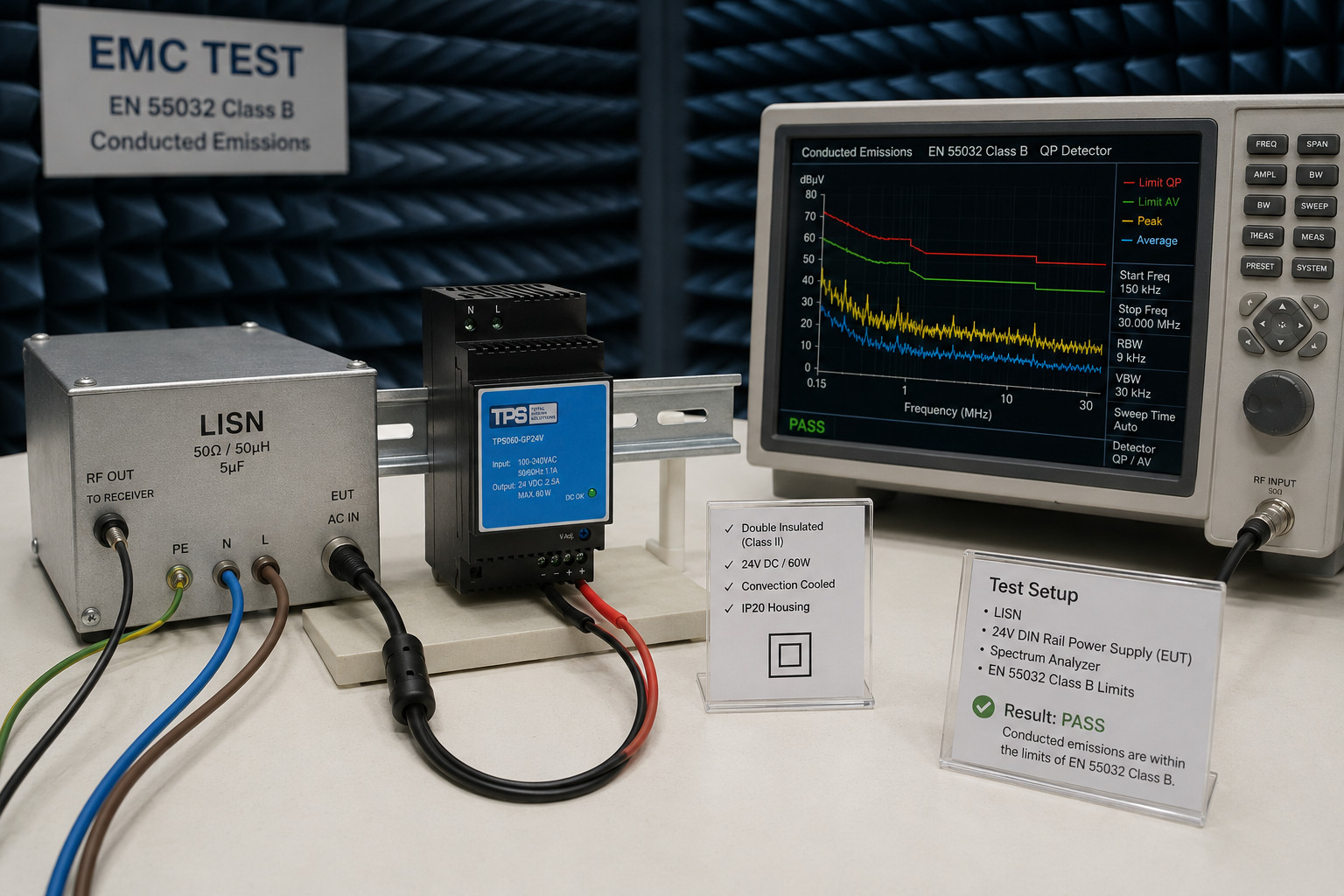
The CE power supply marking rests on a complete Technical File that we own. We can therefore support OEM customers with the documentation they need for their own end-product certification. Our EMC power supply performance, verified in-house, consistently achieves EN 55032 class B with 6 dB margin. This buffer absorbs cumulative emissions when multiple power supplies mount side-by-side in a dense panel.
The Systems Engineering Difference: A Summary of the Platform
Every parameter in the upcoming range of power supplys flows from the design philosophy described above. We validated the following performance envelope through external accredited laboratories on pre-production samples:
Validated Performance at a Glance
- Input: 90–264 VAC / 120–370 VDC, active inrush limiting, EN61000-3-2 compliant.
- Output: 12 V models adjustable from 12V to 15V; 24 V models adjustable 24–28 V, ripple below 50 mVpp.
- Hold-up time: minimum 20 ms at 230 VAC, full load.
- Enclosure: IP20 power supply, double insulated, protection class II.
- Cooling: convection cooled power supply, fanless, 0 to 50℃ power supply at full load, cold start -25 °C.
- Altitude: 3000m altitude power supply without derating.
- Mounting: DIN Rail TS 35/7.5 and TS 35/15.
- Reliability: 350000 hours MTBF (Telcordia SR-332, 50 °C), HALT-verified design margins.
- Warranty: 5 year warranty power supply as standard.
- Certifications: CE power supply, EMC power supply (EN 55032 class B), Low Voltage Directive power, EN60601-1 power supply, EN61347-2-13 power supply, IEC62368-1 power supply.
- Protections: overvoltage protection power, overtemperature protection power, auto recover protection on all faults.
Design Authority from Silicon to Schematic
What distinguishes this platform is not a single headline figure. It is the fact that every element — from the transformer winding structure to the thermal gap filler, from the overvoltage comparator threshold to the EMC choke inductance — is under our direct design authority. When a European machine builder requests a specific power rail sequencing, a custom output voltage, or a din rail ups integration that fits an existing cabinet, we can respond at the schematic level. We are not constrained by an ODM’s reference design or a distributor’s stock list.
The self-manufactured family of dc power supplies that we will soon launch is the physical expression of this engineering philosophy. We built it to serve the European industrial landscape with the ruggedness, adaptability, and long-life predictability that comes from owning the complete design. We invite system architects, control panel builders, and OEM technical leads to engage with us early. Let us not simply discuss lead times, but help shape the final behaviour of the 12v power supply or 24 volt power supply that will live inside your machines, often longer than the machines themselves are under warranty.than the machines themselves are under warranty.