

System integrators, panel builders, and procurement teams in factory automation rarely lose production time because the PLC logic is wrong. They lose time—and uptime—when the 24V DC rail sags below 20V during a mains brownout, when an inductive load trips the power supply’s overcurrent protection. Or when the power supply documentation cannot support the CE technical file during factory acceptance testing.
TPS Elektronik’s industrial power supply solutions for PLC control cabinets built to eliminate that risk: 24V DIN rail supplies with 170% power boost, 20ms hold-up time at full load. And compliance documentation aligned with IEC 61131-2 and EN 61010.
Discuss your PLC control cabinet power requirements with TPS →
1. What is a PLC control cabinet power supply?
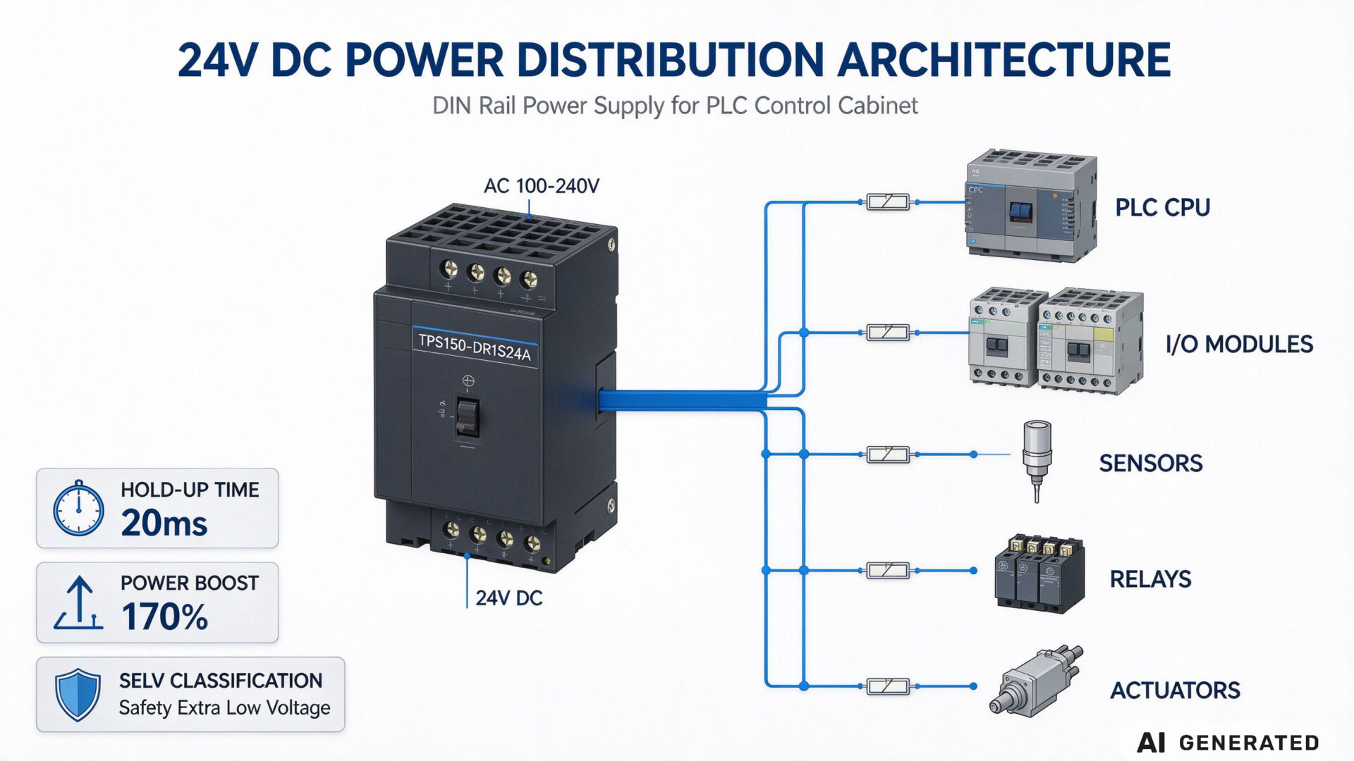
A PLC control cabinet power supply is the AC/DC conversion stage that delivers regulated 24V DC to the programmable logic controller, I/O modules, sensors, relays, and communication devices inside an industrial control panel. Unlike general-purpose power supplies, PLC cabinet power supplies must meet specific requirements for hold-up time, transient response, and safety isolation that defined by the IEC 61131-2 standard for programmable controllers.
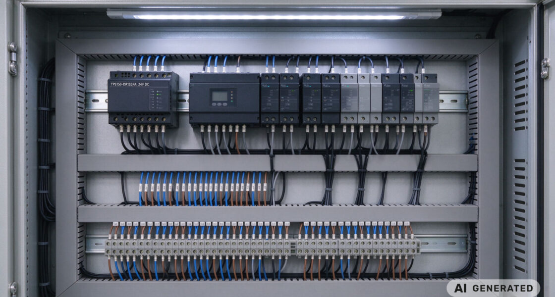
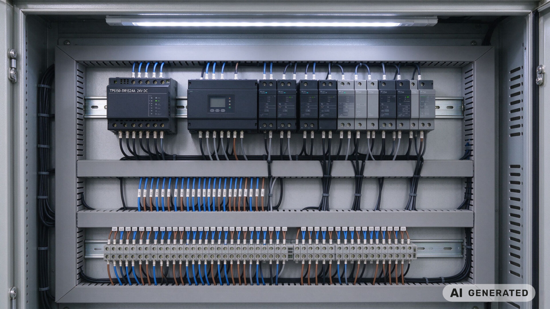
The 24V DC rail is the electrical backbone of factory automation. A single DIN rail power supply typically feeds the PLC CPU, dozens of sensors, and numerous actuators. The power supply must maintain stable output voltage under widely varying load conditions—from near-zero current when the machine is idle to full rated current when all outputs are active.
1.1 Why 24V DC is the standard for factory automation
The 24V DC voltage level has been the backbone of industrial control for decades because it represents a deliberate engineering trade-off. The voltage is high enough to drive relays, contactors, and solenoid valves over long cable runs without excessive current or voltage drop. Yet it is low enough to be classified as Safety Extra-Low Voltage (SELV) under IEC 61140. Which inherently limits the risk of electric shock and simplifies panel design.
For PLC power supply solution specification, the 24V DC rail must maintain voltage within the PLC’s tolerance window. Typical PLCs accept 24V DC with a tolerance of −15% to +20%, meaning the power supply output must remain between 20.4V and 28.8V under all load and temperature conditions. If the voltage sags below approximately 20V, the PLC may enter an undefined state and sensors may generate erroneous signals.
1.2 Hold-up time: the specification that prevents PLC resets
Hold-up time defines how long the power supply output remains within regulation after the AC input is removed. Under IEC 61131-2, DC power supply units for PLC systems classified as PS1 or PS2 based on their ride-through capability. For PS2 classification—the requirement for most industrial control applications—the power supply must maintain output during input interruptions of up to 10 milliseconds, with a minimum of 1 second between consecutive interruptions.
In practical terms, a power supply with 20ms hold-up time at full load and 230V AC input allows the PLC to ride through a brief mains interruption without triggering a reset or losing memory. This is particularly critical in facilities where the mains supply is subject to voltage dips caused by large motor starts, welding equipment, or grid disturbances.
2. TPS industrial power supply solutions for PLC cabinets
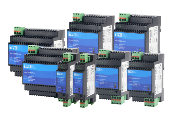
TPS Elektronik offers a portfolio of 24V DIN rail power supplies engineered for PLC control cabinet integration, with power ratings from 10W to 320W and output voltages of 12V, 24V, and 48V. The portfolio includes the TPS010-GP24V (10W), TPS030-GP24V (30W), and the TPS150-DR1S24A (150W) with 170% power boost capability.
2.1 170% power boost for inductive load start-up
One of the most common causes of spurious power supply shutdown in PLC cabinets is the inrush current drawn by inductive loads. When solenoid valves, motor contactors, or capacitive input stages energize, they draw a surge of current that can exceed the power supply’s rated output by 150–200% for a brief period. If the power supply’s overcurrent protection responds too quickly, the entire 24V rail collapses and the PLC loses power.
The TPS150-DR1S24A addresses this with a 170% power boost capability for up to 10 seconds, with automatic recovery. This allows the power supply to deliver up to 10.7A momentarily while maintaining regulation. Which absorbing the inductive load start-up without triggering protection shutdown.
2.2 Thermal management and derating in enclosed cabinets
Power supply efficiency directly affects the thermal load inside a sealed control cabinet. The TPS150-DR1S24A achieves 93% efficiency at 220V AC and maximum load. Which meaning only 10.5W of the 150W output is dissipated as heat inside the cabinet. This reduces the thermal burden on neighboring PLC components and simplifies cabinet cooling design.
TPS DIN rail power supplies are specified for operation from 0°C to 70°C with derating from 50°C to 70°C. In enclosed cabinets where internal temperature may exceed ambient by 10–15°C, this derating curve determines the maximum continuous load the power supply can support. TPS provides thermal derating documentation that allows panel builders to select the appropriate power rating based on actual cabinet conditions.
For a deeper examination of DIN rail power supply selection and integration, see the element and material technology guide and the element testing laboratories resource.
3. Redundant power supply configurations for uptime-critical lines
For production lines where a power supply failure would halt the entire operation, a single power supply is a single point of failure. The standard industrial solution is a 1+1 redundant configuration: two identical power supplies connected through a redundancy module that provides diode decoupling and current sharing.
In this configuration, both power supplies operate in parallel under normal conditions, each carrying approximately 50% of the load. If one unit fails, the redundancy module automatically isolates the failed unit and the remaining power supply takes over the full load within milliseconds—fast enough that the PLC does not detect a voltage interruption. The redundancy module also prevents reverse current from flowing into the failed supply, which could otherwise damage the remaining unit.
For uptime-critical PLC control cabinets in automotive, pharmaceutical, and continuous process manufacturing, 1+1 redundancy is often specified alongside a 30% power margin to account for derating and future expansion. The combined system availability can exceed 99.99%, reducing unplanned downtime from hours per year to minutes.
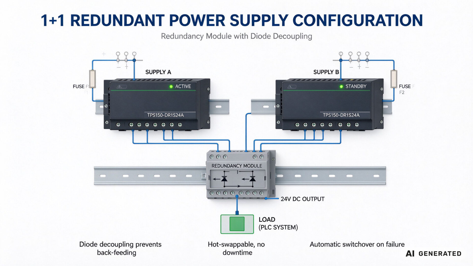
TPS can support redundancy module selection and configuration as part of its PLC control cabinet power supply solution. The quality assurance customer case documents how TPS handles uptime-critical automation projects.
4. Compliance evidence: IEC 61131-2, EN 61010, and CE documentation
For PLC control cabinet power supplies, regulatory compliance is not merely a checkbox—it is documented evidence that the power supply meets the electrical service conditions defined for programmable controllers. The applicable standards are:
- IEC/EN 61131-2: Programmable controllers — Equipment requirements and tests. This standard defines the electrical service conditions, including the allowed input voltage range and the ride-through requirements (PS1 and PS2 classification). Power supplies for PLC systems must demonstrate compliance with the hold-up time and voltage interruption requirements of this standard.
- EN 61010-2-201: Safety requirements for electrical equipment for measurement, control, and laboratory use — Particular requirements for control equipment. This standard covers the safety aspects of stand-alone power supplies used in industrial control applications, including SELV/PELV requirements and isolation.
- EN 61000-6-2 / EN 61000-6-4: Generic immunity and emission standards for industrial environments. These standards define the EMC performance that the power supply must achieve when integrated into an industrial control cabinet.
TPS provides compliance documentation including IEC 61131-2 hold-up time test reports, EN 61010 safety certificates, and CE marking technical files. This documentation package supports the panel builder’s CE marking obligations and provides the evidence required during factory acceptance testing. The metal testing and compliance guide and the global sales partner compliance case study document TPS’s approach to compliance-driven projects.

5. RFQ checklist for PLC control cabinet power supplies
To streamline quotation and evaluation for industrial power supply solutions, provide the following information when submitting your RFQ:
- Power rating and output voltage: Required continuous load (sum of all 24V DC loads with simultaneity factor) and whether 12V, 24V, or 48V output is required
- Peak load profile: Amplitude and duration of inductive load start-up surges (solenoid valves, contactors, motors)
- Redundancy requirement: Single supply or 1+1 redundant configuration with redundancy module
- Cabinet thermal conditions: Expected internal ambient temperature and airflow constraints for derating calculation
- Compliance documentation: Required standards (IEC 61131-2, EN 61010) and documentation format for CE technical file
- Mounting configuration: DIN rail type (TS 35/7.5 or TS 35/15) and available cabinet width
- Project scale: Prototype quantity, series production volume, and delivery schedule
TPS’s engineering team can support load calculation, thermal derating analysis, redundancy configuration, and compliance documentation review as part of the RFQ process. The global sales partner service covers the full path from component selection to regional deployment.