The Three Phase Pad Mounted Transformer from TPS ELEKTRONIK is a factory-direct, American standard (ANSI/IEEE) distribution solution built for safe, stable, and efficient power conversion in demanding field installations. Supporting a wide rated capacity range from 75 kVA to 3735 kVA, this unit is engineered to handle the rigorous demands of modern industrial and utility applications.
Whether you are designing a power system for a commercial building, a petroleum mining site, or a renewable energy plant, this Outdoor Pad Mount Transformer delivers unparalleled reliability through its oil-immersed cooling, high-quality copper windings, and isolated HV/LV compartment design.
1. Core Architecture: The Pad Mount Distribution Transformer
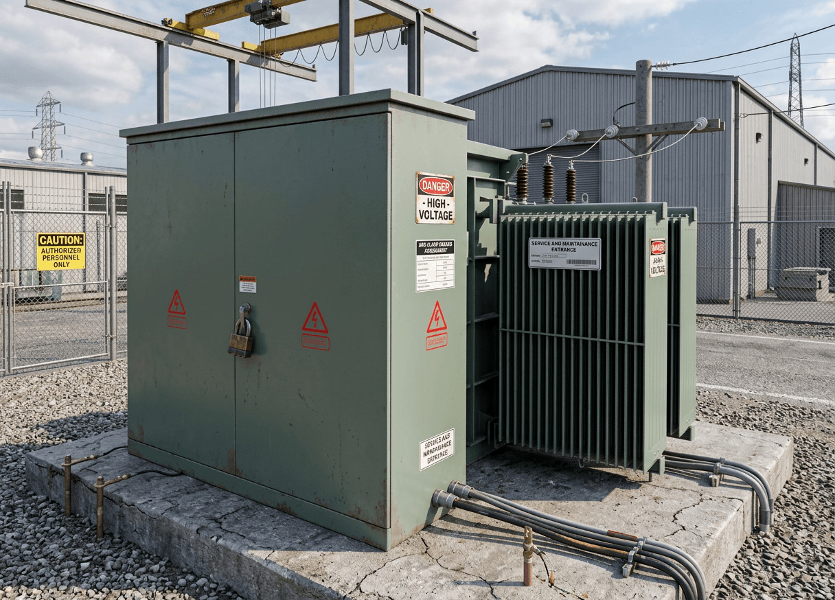
Unlike traditional pole-mounted transformers or indoor dry-type units, the Pad Mount Distribution Transformer is designed for ground-level outdoor installation. It sits on a concrete pad and features a tamper-resistant, Lockable Cabinet Transformer design that eliminates the need for protective fencing in many jurisdictions.
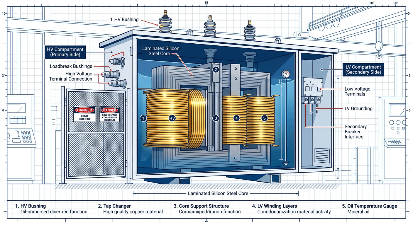
A defining feature of the TPS ELEKTRONIK design is the Isolation Compartment Design. The cabinet is strictly divided into High Voltage (HV) and Low Voltage (LV) sections. This physical separation significantly improves operator safety during routine maintenance, reduces electromagnetic interference, and simplifies the overall operation. The dead-front construction ensures that no live parts are exposed when the cabinet doors are opened, strictly adhering to ANSI/IEEE C57.12.34 standards for pad-mounted equipment.
For projects requiring different form factors, you may also explore our comprehensive range of power distribution transformers.
2. Electrical Specifications & Capacity Range
Flexibility in voltage and capacity is paramount for utility and industrial applications. This 75kVA to 3735kVA Three Phase Pad Mounted Transformer offers a massive operational bandwidth, making it suitable for everything from small commercial complexes to massive industrial manufacturing plants.
- Primary (HV) Voltage: Customizable from 34.5 kV down to 4.16 kV (including common ratings like 4160GrdY, 24940GrdY/2400, and 14400V).
- Secondary (LV) Voltage: Customizable from 120V up to 600V (including 208GrdY, 600GrdY/120, and 347V) to perfectly match site-specific load requirements.
Efficiency is a critical metric for any Utility Transformer. This series is optimized to minimize energy waste, featuring a typical no-load loss ranging from 180W to 4125W, and an on-load loss from 1250W to 37875W, depending on the specific model and kVA rating. Lower losses translate directly to reduced operational costs over the transformer’s multi-decade lifespan.
If your application requires specific voltage regulation, consider reviewing our OSG/LOSG Three Phase Autotransformers for complementary voltage control solutions.
3. Oil Immersed Cooling & High-Efficiency Materials
Thermal management is the lifeblood of a high-power transformer. The TPS Oil Immersed Transformer utilizes premium dielectric fluid to insulate internal components and dissipate heat effectively. Coupled with a Radiator Cooled Transformer design, the external corrugated fins provide a massive surface area for natural convection cooling, ensuring stable thermal performance even under continuous heavy loads.
Internally, the build quality is uncompromising. As a true Copper Winding Transformer, it utilizes high-purity copper coils rather than aluminum. Copper provides superior electrical conductivity, lower resistance, and better short-circuit mechanical strength. Combined with an excellent, low-loss silicon steel iron core, the transformer delivers fast transient response, high efficiency, and exceptional long-term reliability.
4. Safety, Protection & Switching Options
An ANSI IEEE Transformer must meet stringent safety and operational criteria. To support advanced protection coordination and convenient field switching, this transformer is equipped with a comprehensive suite of standard service and safety elements:
- Bayonet Fuse Transformer Design: Allows for easy, dead-front replacement of fuses, protecting the transformer from secondary faults and severe overloads.
- Four Position Load Switch: Enables operators to easily reconfigure the network feed (e.g., loop feed systems) without moving high-voltage cables.
- Tapping Switch: Allows for manual voltage adjustments (de-energized) to compensate for grid voltage drops.
- Comprehensive Monitoring: Includes an oil level indicator, pressure indicator, thermometer, and a critical pressure relief valve to prevent catastrophic failures during internal fault conditions.
For specialized medical environments where isolation is even more critical, engineers often pair primary distribution with secondary Three Phase Medical Isolation Transformers.
5. Industrial & Utility Applications
The robust, application-ready build of the Three Phase Pad Mounted Transformer makes it the backbone of modern infrastructure. Its footprint (ranging from 1430*910*1930mm to 2680*2060*4080mm) and weight (645kg to 14400kg) are optimized for standard concrete pad installations.
Key Application Sectors:
- Industrial Power Transformer: Heavy manufacturing, automation equipment, and processing plants requiring stable, high-capacity power.
- Commercial Buildings: Shopping malls, hospitals, and data centers where underground wiring and aesthetic, secure outdoor cabinets are preferred.
- Petroleum & Mining Sites: Harsh environments that demand the ruggedness of an oil-immersed, sealed system.
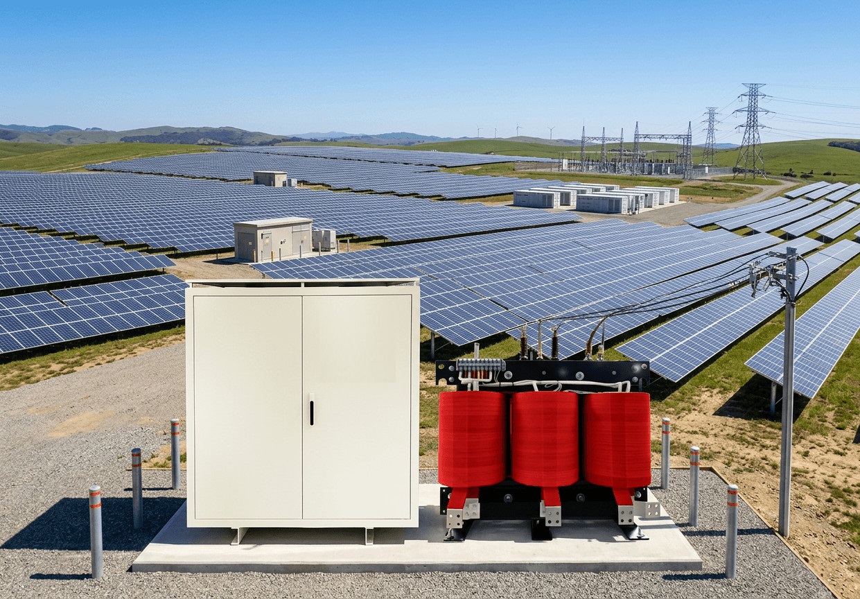
- Renewable Energy: Solar farms and wind power sites. (For specific PV applications, see our Photovoltaic Isolation Transformers).
6. RFQ Checklist for Procurement
To ensure a rapid and accurate quotation process for your 34.5kV to 277V Transformer (or other voltage configurations), procurement teams and electrical engineers should prepare the following details when submitting an RFQ to TPS ELEKTRONIK:
- Rated Capacity (kVA): Specify your requirement within the 75 kVA to 3735 kVA range.
- Primary & Secondary Voltages: Exact HV and LV requirements (e.g., 34.5kV Delta to 480Y/277V).
- Feed Type: Radial feed or Loop feed configuration.
- Winding Material: Confirm preference for Copper Winding (standard for high efficiency) or Aluminum.
- Accessories Required: Specify if you need a bayonet fuse, four-position load switch, specific gauges, or drain valves.
- Compliance Standards: Confirm ANSI/IEEE requirements or specific local utility regulations.
Ready to configure your system? Explore our broader power supply solutions to complete your industrial setup.
7. Frequently Asked Questions (FAQ)
Q1: What is the advantage of a Pad Mount Distribution Transformer over a pole-mounted unit?
A: Pad mounted transformers are installed on the ground, allowing for underground power routing. This eliminates unsightly overhead wires, reduces weather-related outages (like wind or falling trees), and provides easier access for maintenance via the lockable cabinet.
Q2: Why choose a Copper Winding Transformer over aluminum?
A: Copper has lower electrical resistance, which reduces load losses and heat generation. It is also mechanically stronger, allowing the transformer to better withstand the physical stresses of short-circuit currents, ultimately extending the unit’s lifespan.
Q3: What is the function of the Bayonet Fuse in this transformer?
A: The bayonet fuse is a safety device located in the HV compartment. It protects the transformer from secondary faults and overloads. Its design allows operators to safely and easily replace the fuse element using a hot stick without exposing themselves to live internal components.
Q4: Can this transformer be used for solar or wind power applications?
A: Yes, the wide capacity range and robust oil-immersed cooling make it highly suitable for renewable energy sites. For specialized solar setups, you can also integrate it with our advanced power supply systems and PV isolation units.
Q5: Does the transformer comply with US standards?
A: Absolutely. The unit is strictly built to ANSI/IEEE standards, ensuring full compliance for utility and commercial distribution projects across North America.


