A Tuesday Afternoon in Stuttgart
The Hidden Cost of Resistive Loads
A validation engineer prepares a long‑duration discharge test on a prototype battery module late one afternoon. The test plan calls for a 0.5C discharge to the end‑of‑discharge voltage, repeated for three cycles, with data logged at one‑second intervals. On paper, this looks straightforward. However, a set of interconnected challenges soon consumes more time and budget than the test itself. The resistive load bank that absorbs the battery’s energy already radiates heat into the room. Consequently, the air conditioning system runs near its capacity.
Over a month, the electricity cost for this test bay approaches the monthly lease cost of the equipment. This expense covers charging the battery from the grid and then removing the waste heat from the discharge. Furthermore, the load bank offers no flexibility in discharge profile. If the test specification changes to require a pulsed discharge or a specific current ramp, the engineer must integrate a separate electronic load, along with additional wiring and control software.
A Gap in the Market
This scene is not unusual. Similar challenges play out every day in test laboratories across Europe. The central problem is not a lack of suitable instruments. Instead, the instruments available often address only one part of the problem. A resistive load solves power absorption but wastes energy. A conventional electronic load offers programmability but still dissipates heat. A regenerative electronic DC load promises energy recovery but may lack the waveform flexibility, communication options, or rack density that modern test systems require.
What the market has been missing is an instrument that approaches the problem from first principles. It must be an energy‑recovering DC load that fits into dense 19‑inch racks and speaks the languages of laboratory and factory automation. It also needs to generate the dynamic load profiles that modern automotive and energy testing demands. This article explores the engineering thinking behind creating such an instrument. It is not a product announcement, though one is close. We discuss design philosophy, technical trade‑offs, and the practical realities of test engineering in Europe.
Why 3U? The Density Decision
Thermal and Mechanical Boundary Conditions
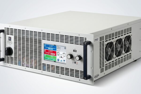
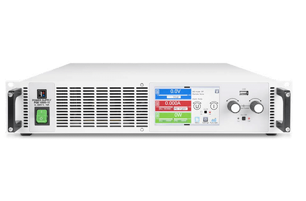
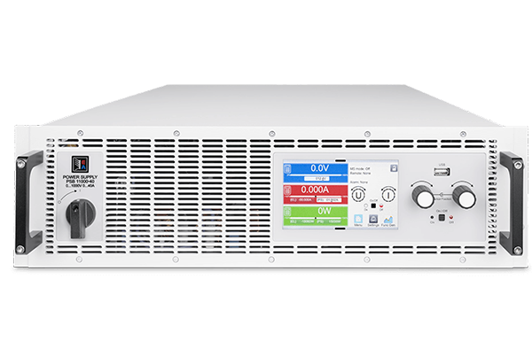
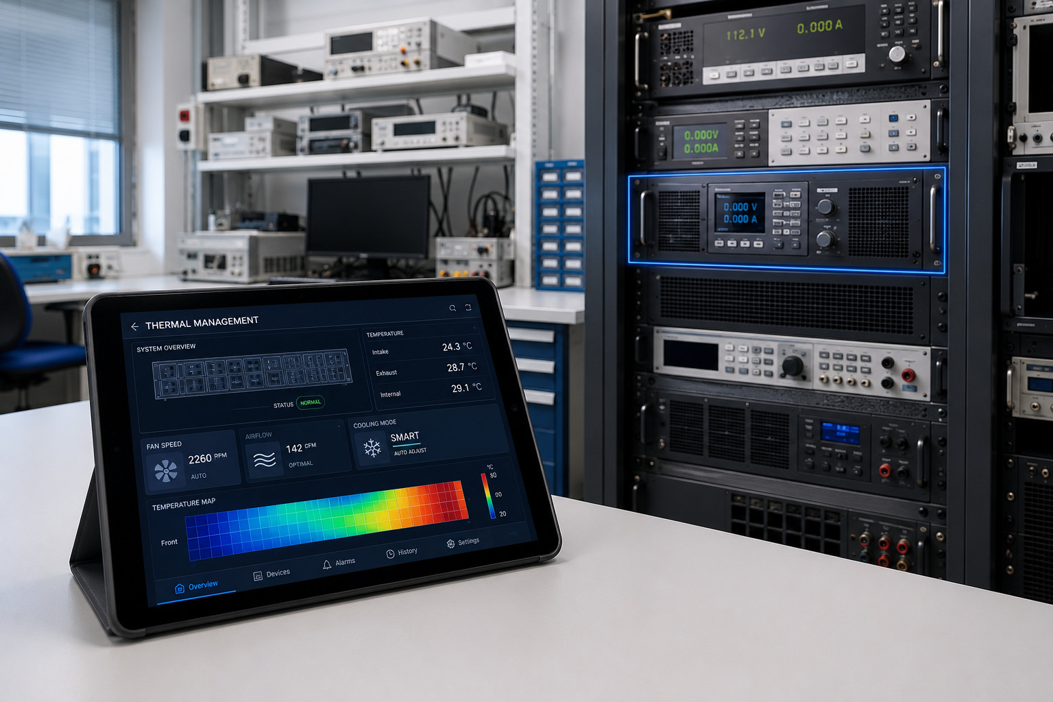
We chose a 3U rack mount chassis for this high‑power instrument after careful deliberation. In a 19 inch installation, every vertical unit counts. A 3U form factor — 133.35 millimetres in height — represents a deliberate compromise. It balances the internal volume needed for power electronics, cooling, and connectors against the need to leave rack space for data acquisition, simulators, and other equipment. A high density 3U DC power supply design starts with one question: how much useful power absorption can we deliver from this constrained volume while maintaining thermal and acoustic characteristics suitable for a laboratory?
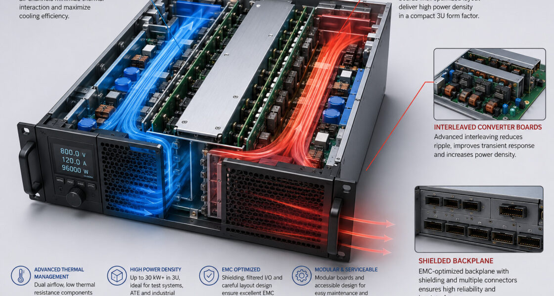
Our engineering team spent considerable time on this question. The answer depends on a cascade of interrelated decisions. The choice of power semiconductor technology affects switching losses, which in turn affect heatsink sizes and required airflow. Similarly, the choice of inverter topology affects internal bus voltages and isolation requirements. Moreover, the decision to include field‑replaceable communication modules imposes additional volume and connector space. None of these decisions could be made in isolation. We therefore defined a set of boundary conditions. The instrument must sustain full rated absorption power at an ambient temperature of up to 50 degrees Celsius. The sound pressure level at the rack front, measured at one metre, must not interfere with normal conversation. The airflow must be front‑to‑rear or side‑to‑side, compatible with standard rack cooling architectures. These boundary conditions, rather than any single specification, drove the internal layout and component selection.
Integrated versus Modular Construction
The result is a high density 3U DC power supply platform that does not push any single technology to its limit. It balances electrical, thermal, and mechanical considerations to make the instrument reliable over years of continuous use. We built the chassis as a single integrated unit — not a collection of field‑swappable power modules. An integrated approach allows tighter thermal coupling between the power devices and the heatsinks, more efficient use of internal volume, and simpler internal wiring. The trade‑off is that the power rating is fixed at the time of manufacture. The benefit is a more robust and thermally efficient design. Users who need higher power can operate multiple units in parallel, a topic we address later in this article.
Energy Recovery as a Starting Point
If a single decision defines the character of this instrument, it is our choice to make energy recovery the default mode of operation, not an optional add‑on. A conventional DC load converts all absorbed energy into heat. For a 10 kW continuous test, this means 10 kWh of heat rejected into the laboratory every hour. Over a year of multi‑shift operation, the energy cost alone can equal the capital cost of the load. The cooling infrastructure required to handle this heat — additional air conditioning capacity, higher‑rated electrical distribution, possibly liquid cooling — adds further expense. For European test facilities where energy costs are high and corporate sustainability goals increasingly link to operational budgets, this situation is no longer tenable.
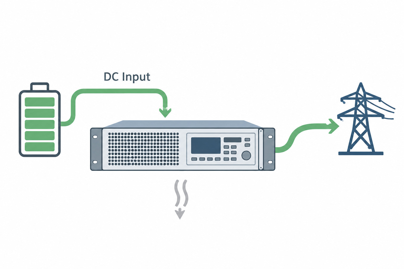
An energy recovery system changes the arithmetic. It converts the absorbed DC power to AC and synchronises with the facility grid, returning up to 95% of the energy. The regenerative grid feedback path uses an active front‑end that shapes the AC current to be sinusoidal and in phase with the grid voltage, maintaining a power factor above 0.99. The instrument rejects only its internal losses into the laboratory — typically a few hundred watts rather than several kilowatts. This fundamentally changes the economics of testing. Long‑duration battery cycling, fuel cell endurance runs, and power converter burn‑in tests become viable without the hidden cost of energy waste.
Grid Interface Engineering
The engineering challenge behind an energy recovery system lies in the grid interface. The grid‑tie inverter must maintain phase lock under all normal operating conditions, including voltage sags, frequency variations, and harmonic distortion common on industrial networks. It must disconnect seamlessly if the grid fails and reconnect without manual intervention when the grid restores. A dedicated digital signal processor runs the control algorithm that manages this process, separate from the load regulation controller. This separation ensures that grid events do not affect the DC‑side measurement. We devoted a significant portion of our development effort to testing the regenerative grid feedback under realistic grid conditions. After all, an instrument that trips offline during a minor grid disturbance would be worse than useless in a production test environment.
Load‑Side Regulation: CC, CV, CP, CR from the Load Perspective
The Four Regulation Modes
A DC load regulates the current it draws from its input. The four fundamental load‑side regulation modes — constant current, constant voltage, constant power, and constant resistance — each address a different test requirement. Constant current mode is the simplest. The instrument draws a fixed current regardless of input voltage, within the compliance range. Constant voltage mode adjusts the current to maintain a set input voltage, which is essential for battery discharge testing where the test must terminate at a precise end‑of‑discharge threshold. In constant power mode, the instrument draws a fixed product of voltage and current, emulating a regulated power converter. The constant resistance mode varies current proportionally to voltage, behaving like a fixed resistive load.
Smooth Mode Transitions
The transition between modes must be smooth. Consider a battery discharge that begins in constant current mode and then transitions to constant voltage mode as the battery voltage approaches the cut‑off. If the control loop introduces even a momentary overshoot or oscillation at the transition point, the accumulated ampere‑hour data can become corrupted. Moreover, the battery may experience conditions outside the test specification. We therefore use a priority‑based control architecture. The mode that first reaches its limit takes authority. A crossover algorithm, tuned to eliminate any discontinuity, handles the transition.
We verified this tuning on a range of real‑world sources. These included batteries with varying internal impedance, DC‑DC converters with output capacitance, and photovoltaic arrays with non‑linear IV curves. The goal was never to publish impressive bandwidth numbers. We simply wanted to ensure that an engineer setting up a test at the end of a long day can trust the instrument to handle transitions correctly.
Modular and Scalable: Thinking Beyond a Single Box
A Common Platform Architecture
Our instrument is a single‑channel unit, but it belongs to a modular 3U DC power supply platform. The platform shares a common control architecture and communication protocol. This is an engineering decision with practical consequences. When we speak of a scalable programmable DC power supply family, we mean one thing. The same SCPI command set, software drivers, and user interface conventions apply whether the test system consists of one unit or twenty. A test script developed on a single‑unit bench system can deploy to a multi‑unit production system without modification. Consequently, the command structure abstracts away the hardware configuration.
Isolated Multi‑Channel Configurations
This scalability also applies to an isolated multi‑channel 3U DC power supply configuration. You can use multiple single‑channel units together with galvanic isolation between their inputs. In testing a stacked battery system, for example, you can connect each unit to a different cell group, with its DC input floating at the potential of that group. This requires careful attention to the isolation rating of the DC input terminals and the common‑mode rejection of the measurement circuitry. We designed the input stage with this use case in mind. The isolation voltage between the DC input and chassis ground, and between adjacent units in a rack, is sufficient for the battery stack voltages commonly encountered in electric vehicle and grid storage applications.
Parallelable Operation and Master‑Slave Current Sharing
The Need for Active Current Balancing
When a single instrument cannot provide enough power absorption capacity, the only practical solution is to operate multiple units in parallel from the same DC source. A parallelable 3U DC power supply design must solve the problem of current sharing. Without active balancing, small differences in cable resistance, connector contact quality, or calibration can cause one unit to draw significantly more current than another. This can lead to thermal stress, premature aging, or even shutdown of the overloaded unit.
Analog Current‑Sharing and Synchronisation
We employ a master‑slave parallel operation scheme that uses a dedicated analog current‑sharing bus between units. You designate one unit as the master. It generates a current reference signal proportional to the desired total load. The slave units read this analog signal and adjust their own current draw to match, maintaining balance to within a small fraction of the total current. Importantly, this analog bus operates independently of any digital communication. Current sharing remains stable even if the Ethernet or fieldbus link is interrupted. The multiple unit synchronization capability ensures that when a load step or waveform sequence triggers, all units in the parallel group begin the transition at the same instant. We achieve this through a simple hardware trigger line, not a complex real‑time network, because the requirement is basic coordination, not sub‑microsecond alignment.
The Case for an Integrated Waveform Engine
Dynamic Load Profiles
Static DC loads answer only the simplest test questions. Real‑world sources — batteries, fuel cells, photovoltaic arrays — experience dynamic loads. A battery in an electric vehicle does not see a constant discharge. It sees pulses from the motor inverter, ramps from auxiliary loads, and transients from regenerative braking. Testing these conditions requires a load that can vary its current draw over time in a controlled, repeatable manner. This is the rationale for function generator integration: we embed a waveform synthesis engine directly in the load’s control firmware, rather than relying on an external arbitrary waveform generator and analog control inputs.
Built‑In Waveform Types
The integrated engine supports the fundamental waveform types needed for dynamic testing. Sine wave mode allows impedance spectroscopy measurements directly on a source, without a separate frequency response analyser. Triangular wave mode provides a linear ramp up and down, useful for thermal cycling and linearity verification. Rectangular pulse mode applies steep current steps to characterise transient response. Trapezoidal wave mode adds user‑defined rise and fall times to the pulses, better emulating real‑world load changes such as motor starts or capacitor inrush. You can superimpose each waveform on a DC offset, applying a small‑signal perturbation on top of a nominal load current. You can configure amplitude, offset, frequency, duty cycle, and ramp time through the same command interface as all other settings. This tight integration eliminates the external waveform generator, the BNC cables, and the impedance matching concerns that accompany separate instruments. Moreover, the waveform generation synchronises perfectly with the load regulation loop.
DIN 40839 and the Arbitrary Waveform Frontier
Automotive Transient Standards
The European automotive industry has standardised a set of conducted transient test pulses under DIN 40839 automotive test. These pulses simulate the electrical disturbances that can appear on a vehicle’s power supply network — fast transients from relay switching, high‑energy surges from alternator load dump, and complex modulated waveforms from electronic systems. To replicate these pulses as load current profiles, the instrument must generate arbitrary current waveforms with sufficient time resolution and bandwidth.
Building Arbitrary Waveforms
Our arbitrary waveform electronic load capability lets you define any current profile as a sequence of time‑value points. You can enter these through the front panel, import them from a CSV file captured from a real‑world measurement, or select them from a pre‑loaded library that includes the standard DIN 40839 pulse shapes. The ramp function represents the simplest form of arbitrary waveform: a linear transition between two current setpoints over a user‑specified time. You use it frequently for battery discharge termination ramp‑downs and for verifying soft‑start behaviour. The IU table function lets you define a static voltage‑current relationship using a lookup table. As the source voltage varies, the instrument automatically adjusts its current draw according to the table, without any external control intervention. This is particularly useful for emulating non‑linear loads such as DC motors, fuel cell stacks, or constant‑power devices with a defined IV characteristic.
Source‑Load Coordination
Note that the arbitrary waveform electronic load controls only the current it draws from the DC input. The external source under test determines the voltage present at the input. To emulate a complete vehicle electrical system transient, the external source must generate the required voltage waveform, with the DC load providing the corresponding current sink. This division of responsibility — source voltage, load current — is inherent in the architecture of a DC load. We designed the arbitrary waveform engine to work in combination with any programmable DC source that can be triggered simultaneously. The multiple unit synchronization bus coordinates the source’s voltage waveform with the load’s current waveform when required.
Battery Discharge Testing and MPP Tracking
Two application areas where a regenerative DC load provides immediate value are battery discharge testing and solar panel MPP tracking measurement.
Battery Discharge Testing
Battery discharge testing is the fundamental method for determining capacity, internal resistance, and aging behaviour. The instrument draws a controlled current, power, or resistance profile from the battery until the voltage reaches a user‑defined cut‑off. It measures and stores the accumulated ampere‑hours and watt‑hours. Furthermore, the energy recovery system returns the extracted energy to the grid, making long‑duration cycling tests economically and environmentally sustainable.
USB data logging writes test data directly to a USB drive, creating a standalone record that does not depend on a network connection. European research environments, where IT policies may restrict persistent network access for test instruments, particularly value this feature. Charging the battery requires an external DC source; the instrument handles only the discharge portion of the test cycle. This separation of charge and discharge functions lets you select the optimal source for charging, independent of the load used for discharging. It also reflects how most battery test laboratories organise their workflows.
Solar Panel MPP Tracking
Solar panel MPP tracking, as we implement it in this instrument, is a measurement function, not a simulation. The load draws current from a real photovoltaic panel or array while sweeping its input voltage across the panel’s operating range. At each voltage step, it calculates and records the power. The MPP tracking function identifies the voltage and current at which the panel delivers maximum power. You use this data to verify panel specifications, to characterise performance under varying irradiance and temperature, and to validate the MPP tracking function of charge controllers and inverters when tested with the actual panel. The instrument’s USB data logging captures the complete IV curve and the derived MPP parameters for reporting and analysis. Consequently, this represents a more direct and physically representative test than using a solar array simulator, because you characterise the panel itself.
The Communication Fabric: Ethernet, USB, RS232, and Fieldbus Modules
A modern test instrument must integrate into a variety of control environments, from a Python script on an engineer’s laptop to a Siemens PLC on a factory floor. The communication interfaces we provide are therefore a fundamental part of the design. They determine how easily you can incorporate the instrument into existing workflows.
Standard Digital Interfaces
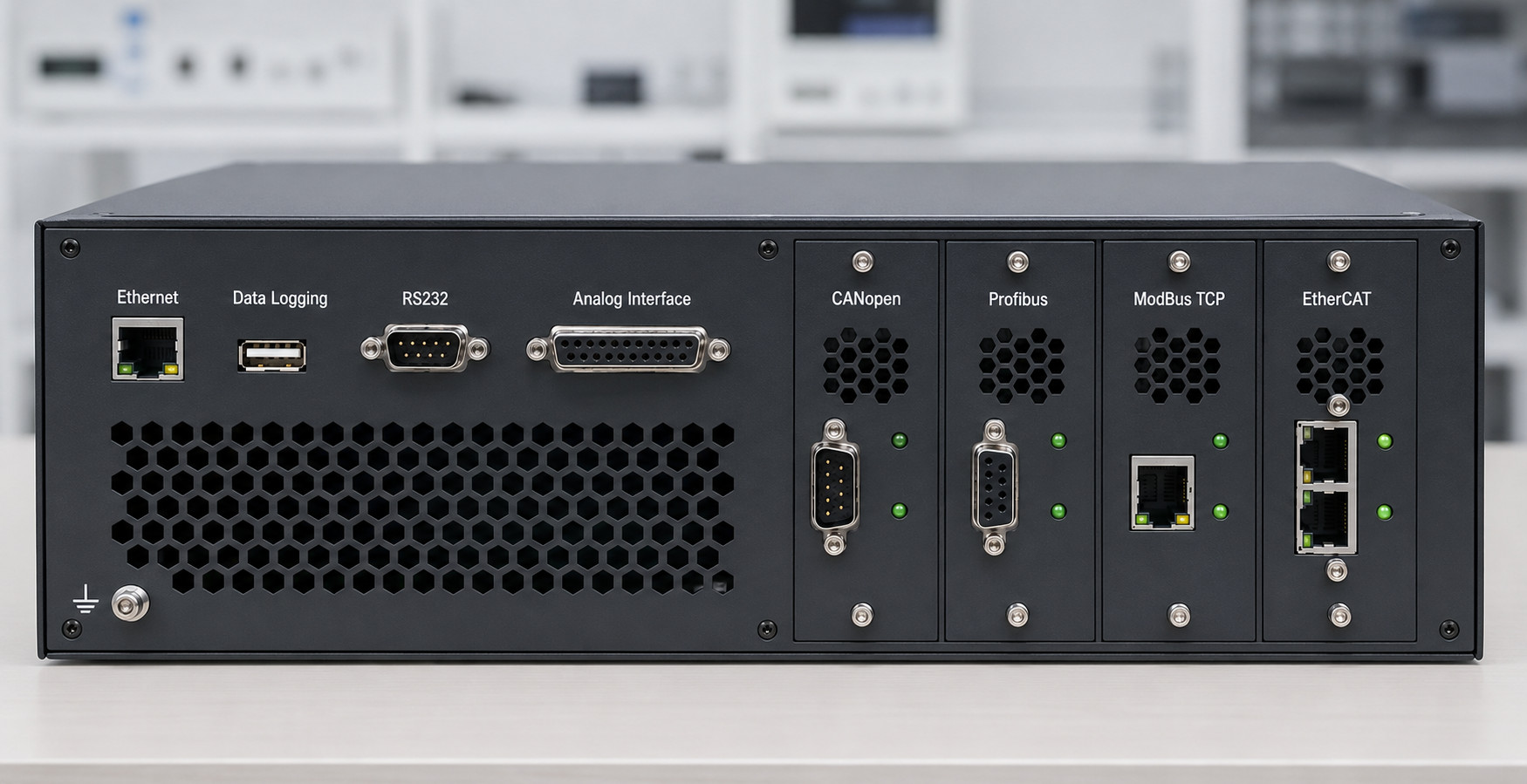
Ethernet remote control serves as the primary interface for laboratory automation. It provides SCPI command access over a standard TCP/IP connection. Most test automation frameworks, including LabVIEW, Python, and MATLAB, use this interface to control the instrument. USB data logging offers an independent, standalone data recording path that writes directly to a removable USB drive. This proves invaluable for overnight tests where network connectivity may be unreliable, and it provides a tamper‑proof record for compliance reporting. We also include an RS232 communication interface for compatibility with legacy systems. Although its bandwidth is limited, its simplicity and reliability mean it remains in use in many long‑established test setups.
Fieldbus Modules and Analog Control
For industrial automation, we support field‑installable communication modules. A CANopen interface module provides direct connection to the CAN‑based networks that dominate automotive test cells and many industrial control systems. A Profibus interface module enables integration with the installed base of Siemens PLCs across European factories. A ModBus TCP interface module supports building management, energy monitoring, and supervisory control applications. An EtherCAT interface module provides hard real‑time communication for applications that require deterministic latency. These modules plug into a dedicated bay on the rear panel. The instrument’s firmware presents a consistent command set regardless of which module is installed. You do not need to learn a different command structure for each fieldbus; the module translates the SCPI command set into the appropriate protocol.
Analog interface programmability rounds out the communication options. A galvanically isolated analog connector provides inputs for current setpoint and outputs for actual current and voltage monitoring, as well as status signals. As a result, you can control the instrument directly from a real‑time simulator, a PLC with analog I/O, or any system that generates an analog control voltage. The analog interface is the preferred control path for hardware‑in‑the‑loop applications. In these cases, the control loop must close in tens of microseconds. Its bandwidth exceeds that of any digital bus. The analog and digital interfaces complement each other. The digital interface handles configuration, sequencing, and data retrieval, while the analog interface handles the high‑speed control path when needed.
Designing for the European Context
The European test equipment market has characteristics that influence instrument design at a fundamental level. Regulatory requirements for safety and electromagnetic compatibility are comprehensive and rigorously enforced. Users value energy efficiency not only for cost reduction but also for alignment with corporate environmental policies. Instrument lifecycles are long. A piece of equipment purchased today may still be in daily use in ten or fifteen years, and users expect calibration support, spare parts, and firmware updates throughout that period. These considerations have shaped our design decisions from the beginning.
We designed the instrument for the 3U rack mount chassis and standard 19 inch installation that are ubiquitous in European laboratories. The mechanical design prioritises service access, so a trained technician can perform maintenance without returning the unit to the factory. The firmware supports field updates via USB or Ethernet, without requiring specialised programming tools. You can perform calibration using standard laboratory equipment. Calibration constants are stored in non‑volatile memory and protected against unauthorised modification. These are not advanced features; they are basic expectations of the European market, and we meet them as a matter of course in our design.
Where We Go from Here
We have developed this platform in‑house, with our own power electronics design, control firmware, and mechanical engineering. Currently, we are completing the final stages of verification and preparing for introduction to the European market. If the challenges and design considerations in this article resonate with your work, we would welcome a discussion. Perhaps you specify test equipment, plan laboratory infrastructure, or manage validation programmes for batteries, power electronics, or renewable energy systems. In any case, we would like to hear about your requirements in more detail. After all, the best instruments emerge from dialogue with the people who will use them. We have always believed that honest technical conversation is the foundation of a productive engineering relationship.