

System integrators, panel builders, and procurement teams rarely lose a prototype window because the design is wrong. They lose it when a machined bracket arrives three days late, when a critical bore is 0.012 mm out and the bearing will not press in. Or when the supplier cannot document the measurement that proves the part is within tolerance.
TPS Elektronik’s high precision CNC prototype machining structured to reduce that risk: DFM review before cutting, feature-specific tolerance planning down to ±0.005 mm, in-process probing and CMM verification, and a fast-track route that targets 3–5 business days for functional prototypes when the DFM is approved and material is in stock.
1. What ±0.005 mm really means in CNC prototype machining
±0.005 mm is five micrometres. For context, a human hair is roughly 70 µm, and a typical CNC machining centre holds ±0.01–0.02 mm on a well-controlled part. Achieving ±0.005 mm requires the machine, the tooling, the workholding, the material, the thermal environment, and the metrology to be aligned—not just a tighter number in the drawing title block.
This is why a credible prototype supplier does not quote ±0.005 mm as a blanket tolerance across every feature. And the number applies to specified critical features: a bearing bore, a datum face, a spigot diameter, a mating interface. General features follow ISO 2768-1 general tolerances unless the drawing states otherwise.
1.1 Tolerance is feature-specific, not a blanket number
A functional prototype typically has two or three features that determine whether it works: the bore that receives a bearing, the face that seats against a sensor, the pattern that aligns with a connector. Those features justify the metrology effort. The remaining 80% of the part—clearance holes, outer profiles, non-critical pockets—does not, and over-specifying them adds cost and lead time without improving function.
And TPS’s DFM review separates the two groups before machining. The output is a drawing mark-up that identifies which features will be probed in-process, which will be verified on the CMM, and which will be checked with standard gauges. That separation is what makes a ±0.005 mm callout achievable within a prototype schedule.
1.2 Preconditions for micron-level results
Five conditions must be met. First, a machine with thermal compensation and a rigid structure. Second, a workholding system that does not distort the part—a zero-point clamping system or a custom fixture, not a standard vise on a thin wall. Third, a CAM strategy that minimizes tool deflection: light radial engagement, constant chip load, and a finishing pass with a sharp tool. Fourth, stress-relieved material, especially for aluminum plate where residual stress moves the part after the first face is cut. Fifth, a temperature-stable metrology environment, because a 1°C change across a 100 mm aluminum part moves the dimension by approximately 2.3 µm.
2. How 3–5 day turnaround is actually achieved
A 3–5 day prototype turnaround is not a promise that every part will ship in that window. It is the result of a workflow that removes the usual waiting points: quotation delay, DFM clarification rounds, material procurement, CAM programming backlog, and inspection queue.
2.1 The fast-track workflow
The clock starts when the purchase order and the approved DFM are in place. Day 0–1: DFM review and quotation, including tolerance rationalization and material confirmation. Day 1–2: CAM programming and fixture preparation; material is cut and stress-relieved if required. The Day 2–4: machining, with in-process probing on the critical features. Day 4–5: CMM verification, deburring, cleaning, and first-article inspection report. Surface finishing such as anodizing or bead blasting is scheduled in parallel where possible, but adds time if the finish affects a critical dimension.
2.2 What extends the timeline
Several factors legitimately extend the window, and a good supplier states them up front rather than missing the date silently. Unusual material that is not in stock adds procurement time. Five-axis features on multiple faces add setups. Thin walls and deep pockets require stress-relief and intermediate inspection. Tight flatness or parallelism across a large face requires a different machining sequence. And any post-machining finish that changes the dimension—hard anodizing, for example—must be sequenced before final inspection.
The practical rule for procurement is to separate “3–5 days for a straightforward functional prototype” from “3–5 days for a complex multi-face part with a critical finish.” The first is routine; the second needs a confirmed schedule in the quotation.
3. Design rules that protect both tolerance and lead time
Design decisions made before the RFQ determine most of the outcome. Five rules matter most for tight-tolerance prototypes:
- Keep the critical datum accessible: A datum that can only be reached from a hidden face forces an extra setup and adds error.
- Avoid thin walls next to tight bores: The wall deflects during clamping and the bore moves after release. If the function requires it, say so in the DFM notes.
- Use standard tool radii: A pocket corner with a radius smaller than the available end mill requires EDM or a second operation.
- Specify tolerance only where it functions: A ±0.005 mm callout on a non-critical clearance hole adds inspection time and cost with no benefit.
- State the finish before machining: If anodizing is required, the pre-finish dimension must be adjusted; discovering this after inspection restarts the cycle.
TPS’s fast RFQ and DFM service reviews these points as part of the quotation, so the design changes happen before the first cut rather than after the first article.
4. How TPS executes precision prototype machining
TPS Elektronik operates CNC milling as part of its EMS scope, with a workflow that connects DFM, machining, and metrology in one sequence.
4.1 DFM and CAM review
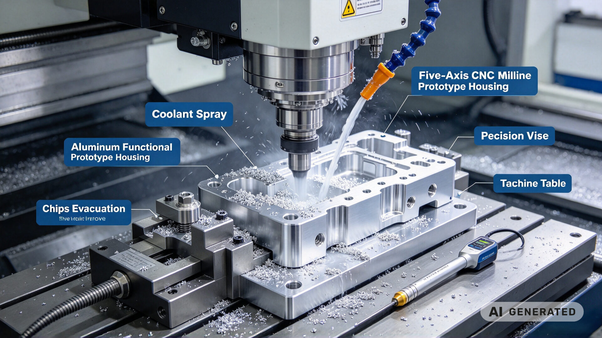
The DFM review checks the tolerance stack, the datum scheme, the workholding concept, and the material condition. CAM programming then uses the review output to define the finishing strategy and the probing points. The types of milling machine guide and the CNC milling machine options resource describe the equipment classes used for different prototype geometries.
4.2 Machining and in-process verification
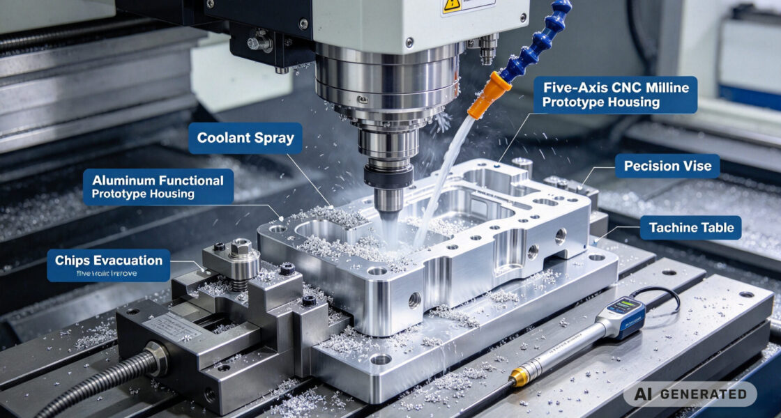
Critical features are probed on the machine before the part is released from the fixture. In-process probing catches thermal drift and tool wear while the part is still clamped, which is far cheaper than discovering the deviation after inspection. Where the geometry allows, the finishing pass is separated from the roughing pass by a stress-relief pause.
4.3 Final inspection and documentation
The first article is measured on a CMM with a calibration traceable to national standards, following the acceptance and reverification principles of ISO 10360-2. The inspection report lists the measured value, the nominal, the tolerance, and the pass/fail result for every critical feature. That report is what the design team uses to release the prototype for functional testing, and what procurement keeps for the project record.
The precision CNC machining resource and the prototype-to-production guide describe how the same process scales from a single functional prototype to a pilot batch.
5. RFQ checklist
To get an accurate tolerance and turnaround quotation for cnc prototype machining, provide the following:
- 3D CAD and 2D drawing: STEP file plus a drawing that identifies which features require ±0.005 mm and which follow general tolerances
- Function description: What the part does and which interfaces are critical—this helps the DFM review prioritize
- Material and condition: Alloy, temper, plate or bar stock, and whether stress-relieved material is required
- Surface finish: Anodizing, bead blasting, passivation, or none, and whether the finish affects a critical dimension
- Quantity: Single prototype, a small functional set, or a pilot batch
- Inspection requirement: First-article report, CMM report, material certificate, and any customer-specific documentation
- Target date: The date the prototype is needed for functional testing, not the date the PO is issued
Providing these details reduces clarification cycles and allows the 3–5 day window to start from a confirmed DFM rather than from an incomplete RFQ.