In the lithium‑ion battery manufacturing chain, the lithium cell formation system and the aging process consume a large share of total energy. Traditional discharge methods waste stored energy as heat. This drives up operational costs and adds extra load on facility cooling. A battery testing power supply built around a bidirectional isolated converter changes this. Instead of wasting energy, the converter returns it to the grid or reuses it in the system. Our design team has developed a high efficiency bidirectional module for energy recycling aging systems. It achieves over 93% round‑trip efficiency. It also maintains ±0.05% current accuracy. The module includes CAN bus communication, integrated protection, and a compact rear‑inlet front‑outlet airflow design. It meets the rigorous demands of modern battery production lines.
This article explains how bidirectional DC‑DC technology transforms cell formation and aging. It covers key design considerations for battery testing applications. It also presents measurable benefits from real‑world deployment. You may design a lithium cell formation system or upgrade an existing energy recycling aging system. Understanding the power stage is critical for quality and energy efficiency.
The Role of Power Conversion in Lithium Cell Formation and Aging
Cell formation is the first charge‑discharge cycle of a newly assembled lithium‑ion cell. During this cycle, the solid electrolyte interphase (SEI) layer forms. The process requires precise current and voltage control. This ensures uniform SEI growth and long‑term cell reliability. A dedicated battery testing power supply must deliver stable current at very low voltages. These voltages sometimes fall below 2.5 V. The supply must also maintain low ripple and fast transient response.
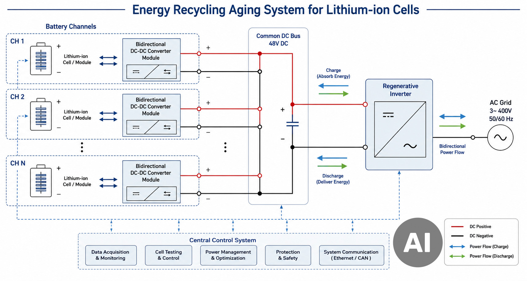
Aging involves repeated charge‑discharge cycles over days or weeks. It identifies defective cells and stabilizes capacity. In a conventional energy recycling aging system, resistive loads dissipate discharge energy as heat. This wastes energy and creates thermal challenges. A bidirectional isolated converter replaces the passive load. The same hardware then operates in two quadrants. It sources current during charge and sinks current during discharge. It returns energy to a common DC bus or back to the AC grid through a front‑end inverter.
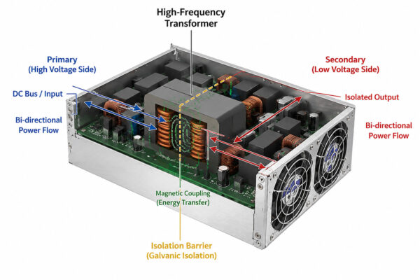
Our design team has made this transition seamless. The module implements bidirectional power flow with synchronous rectification on both sides. The high‑voltage side and the low‑voltage side both use this method. This eliminates diode forward drops. It also enables true four‑quadrant operation. The same unit can handle both charging and discharging. No hardware reconfiguration is required.
Key Features of a Bidirectional DC-DC Module for Battery Testing
- High Efficiency Bidirectional Module – Reaches 96.5% peak efficiency and over 93% round‑trip efficiency at rated power. This reduces energy costs and heat in high‑density cabinets.
- Bidirectional Isolated Converter – Provides galvanic isolation between the battery side and the DC bus. This enhances safety and allows floating battery channels.
- Wide Voltage and Current Range – Supports battery voltages from 0 V to 5 V. It handles currents up to 100 A per channel. This suits various cell chemistries and capacities.
- CAN Bus Communication – Uses an integrated CAN 2.0B interface with a standard protocol. It allows real‑time monitoring, parameter setting, and fault reporting. Large‑scale system integration needs minimal engineering effort.
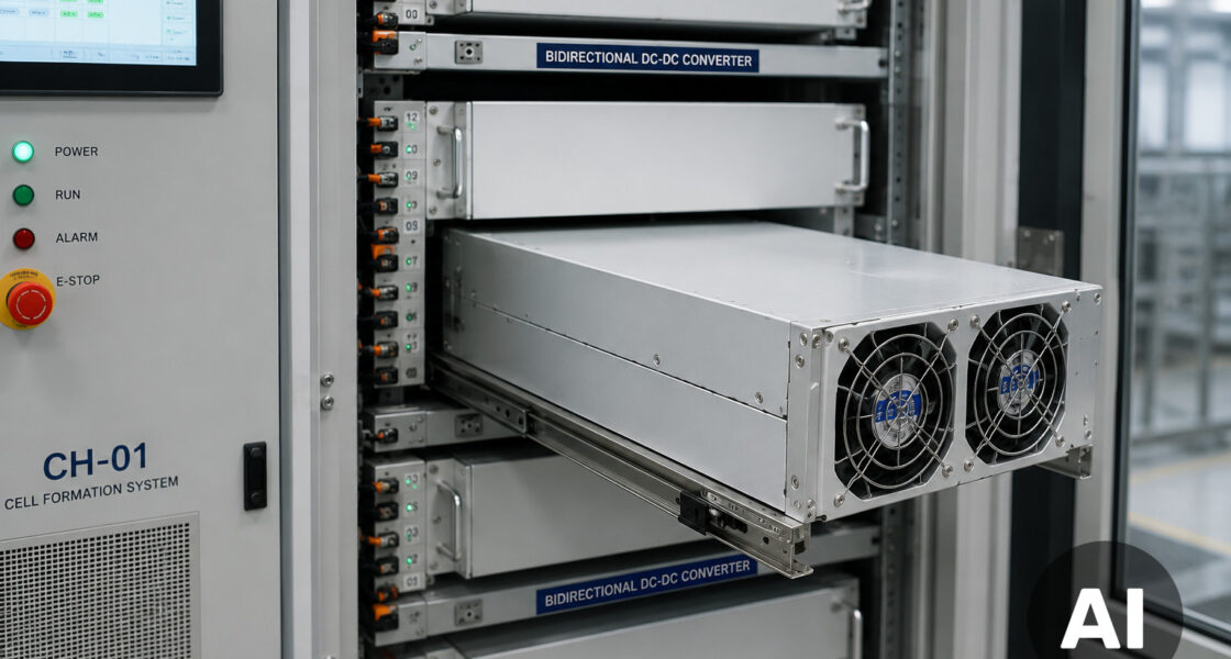
- Rear‑Inlet Front‑Outlet Airflow – Designed for rack‑mount installation. The forced air cooling path aligns with typical cabinet airflow. This prevents hot air recirculation and reduces internal temperature rise.
- Intelligent Fan Control – Adjusts fan speed automatically based on internal temperature and load. This minimizes noise during low‑power operation and extends fan life.
- Comprehensive Protection – Includes over‑voltage, over‑current, over‑temperature, and reverse‑polarity protection. Safe operation continues even under abnormal conditions.
These features are not just specifications. They result from iterative design refinements. We based them on feedback from battery testing equipment manufacturers and end users. Our team has validated each parameter through extensive testing in real formation and aging lines.
How Energy Recycling Works in a Formation System
A multi‑channel formation system processes hundreds or thousands of cells at once. Each channel needs its own power stage. It must charge and discharge. A bidirectional isolated converter module handles one or several channels. This depends on the power rating. During charging, the converter draws energy from the DC bus. It delivers a precisely controlled current to the cell. During discharging, the converter reverses its power flow. It boosts the cell’s low voltage to the DC bus level. Then it feeds energy back into the system.
The discharged energy is not lost. The DC bus is shared among all channels. Discharging cells supply energy to the bus. Other charging channels use that energy at the same time. Surplus energy can be inverted back to the AC grid. This further improves plant efficiency. Our module’s high efficiency design keeps conversion losses low during energy transfer.
Design Considerations for Battery Testing Power Supplies
Designing a power supply for lithium cell formation differs from designing a general‑purpose DC source. Pay special attention to these aspects:
Low‑Voltage Operation – Lithium cells operate from about 2.5 V to 4.2 V. A buck‑derived topology must handle duty cycles near 0% during low‑voltage charging. Our module uses a synchronous buck‑boost or isolated full‑bridge topology. It maintains stable operation down to 0 V output. This is essential for initial formation when cell voltage is near zero.
Current Accuracy and Ripple – The SEI formation process is sensitive to current ripple. Excessive ripple can cause non‑uniform lithium plating. It shortens cell lifetime. Our battery testing power supply achieves current ripple below 0.1% RMS. Current setpoint accuracy is ±0.05% full scale. A high‑bandwidth current loop and interleaved power stages make this possible.
Thermal Management in Dense Cabinets – Formation systems often pack many channels into one rack. The rear‑inlet front‑outlet airflow of our module aligns with the cabinet’s natural cooling path. This prevents hot spots and allows higher channel density. The intelligent fan control reduces noise during low‑load operation. It also ensures reliable operation up to 50°C ambient temperature.
Communication and Synchronization – In a 512‑channel system, the host controller must communicate with every power module. CAN bus communication is the preferred interface. It offers robustness and multi‑master capability. Our module supports 11‑bit and 29‑bit identifiers. Baud rates are configurable up to 1 Mbps. The command set covers voltage/current setting, status readback, and fault flagging.
Case Study: Energy Recycling in a 512‑Channel Aging System
Our team ran a field test in a 512‑channel energy recycling aging system for 18650 cells. Each channel handled 10 A charge/discharge. We divided the system into 64 groups. Each group used one bidirectional DC‑DC module with eight channels per module. The modules connected to a common 48 V DC bus. A regenerative inverter tied the bus to the AC grid.
During discharge, the modules returned energy to the DC bus. The average efficiency was 92.8%. The regenerative inverter fed the surplus back to the grid. Over 30 days, the system saved 35% energy compared to a resistive‑load aging system. The precise current control also reduced cell rejection rates by 0.4%. This directly improved yield.
Protection and Reliability Requirements
A reliable bidirectional converter in battery manufacturing must withstand continuous operation. It must handle frequent power cycling and occasional abnormal events. Our module includes multiple layers of protection. Hardware‑based fast over‑current shutdown and software‑based over‑voltage and over‑temperature limits work together. The protection function power module also adds input reverse‑polarity protection and output short‑circuit protection. A single channel failure does not affect the whole system.
Reliability improves with conservative component derating and a robust thermal design. The forced air cooling system uses high‑quality ball‑bearing fans. They last 70,000 hours at 40°C. The rear‑inlet front‑outlet airflow keeps dust away from critical components. Positive pressure inside the module supports this.
Compliance and Global Standards
Battery testing equipment operates worldwide. Power modules must meet international safety and EMC standards. Our module complies with UL standards power module (UL 62368‑1), CE standards power module (IEC/EN 62368‑1), and CCC standards power module (GB 4943.1). These cover North America, Europe, and China. For electromagnetic compatibility, the module meets EMC compliant EN55032 Class B limits. This applies to conducted and radiated emissions. Pre‑compliance testing shows at least 6 dB margin.
These certifications reflect a design philosophy that prioritizes safety, electromagnetic hygiene, and long‑term reliability. Our team has invested in pre‑compliance testing and certification support. This reduces the burden on customers when they bring systems to market.
Conclusion and Key Parameters
Bidirectional isolated converters are now essential in lithium cell formation and aging systems. They enable bidirectional energy flow and energy recycling. This reduces operational costs and improves cell quality. Our design team has delivered a high efficiency bidirectional module. It combines precise current control, robust communication, and global compliance. It is ready for the next generation of battery testing equipment.