

A 1U 19-inch chassis can free valuable rack space, but only when the complete assembly fits, cools correctly, and remains serviceable. For OEMs, system integrators, panel builders, and procurement teams, the buying decision starts with the mechanical drawing and ends with an agreed delivery scope. The TPS 1U chassis BJ9900001 provides a documented starting point for compact rack electronics and power-related assemblies.
Review the TPS 1U chassis product listing for the base product, or discuss your 19-inch enclosure requirements with TPS when the project needs modified panels, another chassis configuration, or coordinated integration. This guide identifies the checks that turn an enclosure inquiry into a technically useful RFQ.

A compact mechanical starting point
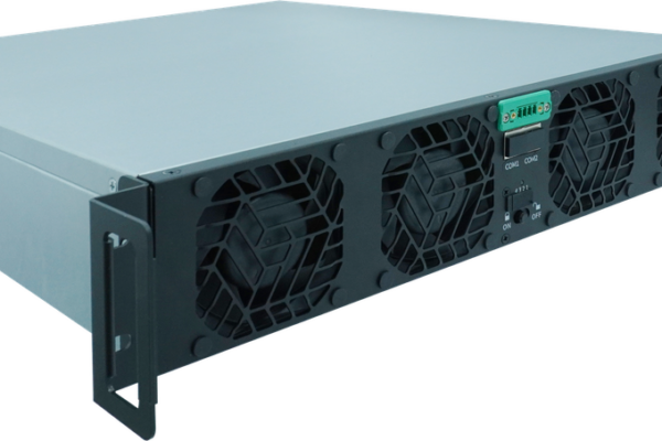
Official TPS product illustration. Openings, accessories, and the delivered configuration must be checked against the approved project drawing.
When a 1U 19-inch chassis fits the project
Consider 1U for low-profile control electronics, interface modules, monitoring assemblies, compact distribution units, or test-system auxiliaries. These are application candidates, not a declaration that every component arrangement fits the standard chassis. The governing constraints are usable internal height, installed depth, heat loss, connector geometry, and the support method in the rack.
For a company owner or product manager, rack density matters when it reduces cabinet size or supports a repeatable equipment platform. That benefit disappears if the design requires difficult assembly, inaccessible terminals, or frequent thermal derating. Engineering should therefore establish the component envelope before procurement compares enclosure prices.
Use a simple decision gate: retain 1U when the complete layout meets height, airflow, insulation, and maintenance requirements with a reasonable margin. If tall magnetics, large terminals, or service tools consume that margin, compare a 2U chassis for rack integration or 3U power-supply integration platform. Changing format early is usually easier than redesigning a released assembly.
Documented dimensions and configuration
The supplied chassis dimension collection identifies BJ9900001 as the 1U ordering reference. Its family overview gives a nominal width and depth of 482.6 × 671 mm; the dimension table provides the more precise values below. Panel height is an external dimension, not the usable internal component height.
| Drawing item | 1U value | Integration check |
|---|---|---|
| Ordering reference | BJ9900001 | Use with the agreed drawing revision |
| Overall width W1 / hole spacing W2 | 482.6 ±0.8 / 465 ±0.3 mm | Front rail and mounting interface |
| Body width W3 / rear width W5 | 449 ±0.8 / 449 ±0.5 mm | Internal layout and rear-panel envelope |
| Handle center distance W4 | 437 ±0.8 mm | Front-panel arrangement |
| Body depth D1 / overall body depth D2 | 666 ±0.8 / 670.5 ±0.8 mm | Cabinet depth and rear clearance |
| Handle depth D3 | 26 / 32 ±0.2 mm | Confirm the selected handle option |
| Panel height H1 / hole spacing H2 | 43.6 ±0.2 / 31.8 ±0.2 mm | Vertical interface and adjacent equipment |
| Handle height spacing H3 | 30 / 32 ±0.3 mm | Confirm the handle configuration |
Depth requires confirmation: the shop specification field and its separate product illustration show 504.2 mm, while the supplied family dimension table shows D2 = 670.5 mm. Do not treat these as interchangeable or assume a selectable depth option. Ask TPS which drawing and dimensions apply to the quoted unit before fixing cabinet depth or releasing CAD.

Confirm the drawing behind the quotation
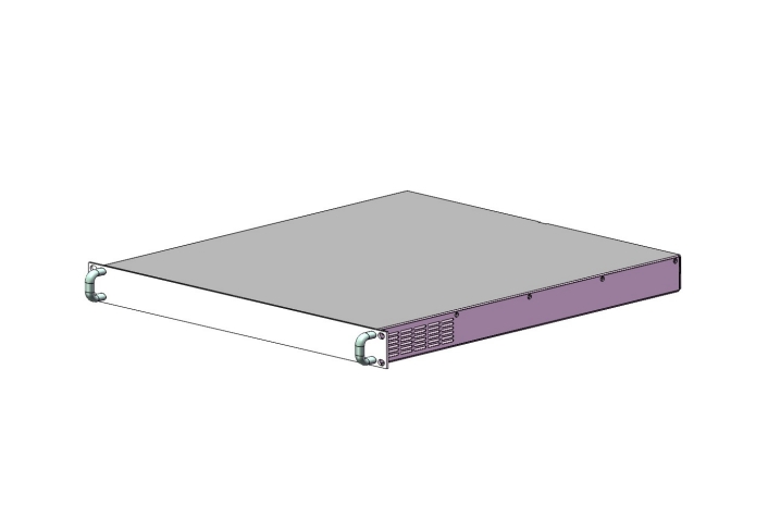
This shop illustration shows a 504.2 mm depth reference. The supplied family table differs; the approved quotation drawing must resolve the applicable configuration.
Selection priorities for the buying team
System integrators and electrical engineers
Build a layout that includes PCBs, mounting hardware, power conversion components, connectors, protective devices, harnesses, and cooling features. Reserve space for insulation requirements and assembly access. A board outline alone is insufficient: component height, screw heads, standoffs, wiring, and the cover all compete for the same vertical envelope.
Panel builders and installation teams
Check rack rail geometry, the load path, rear support, cable entry, and access after installation. Establish whether equipment is serviced in place or withdrawn from the cabinet. Handles shown in an illustration do not establish an allowable lifting load, and an enclosure front flange should not be assigned an unsupported load without engineering review.
Procurement, product managers, and business owners
Compare offers against the same drawing, finish, accessories, and quantity. Separate the base enclosure price from tooling, panel machining, brackets, wiring, assembly, and validation. For a series product, include change control and replacement-panel availability in the discussion. These details often matter more to total project cost than a small difference in the empty chassis price.
Rack installation and service access
Plan the installed envelope from front to rear. Include handles ahead of the rails, chassis depth, rear connectors, mating plugs, cable bends, and the cabinet door. Confirm whether the drawing datum includes each protrusion. An apparently suitable cabinet can become unusable when a rear connector or power cable occupies the final clearance.
Support selection depends on loaded mass, center of gravity, rail geometry, handling, and transport conditions. Ask whether shelves, brackets, or slide rails are required and whether they are included. The supplied specification does not provide an allowable chassis load; the rack support concept therefore needs a separate agreement.
Review maintenance as a physical task: can a technician reach the fasteners, remove the cover, inspect the protective-earth connection, and replace a board without damaging cables? Define power isolation and disconnection steps for the completed equipment. If several assemblies share one rack, the 15U cabinet integration guide offers a useful starting point for cabinet-level space planning.
Evaluate the installed envelope
Product view for enclosure planning. Cable bends, rear connections, internal mounting features, and support hardware are project-specific.
Cooling and electrical integration
Start thermal selection with internal losses in watts, rather than the output power of the equipment. Identify concentrated heat sources and their temperature limits. Specify inlet temperature, duty cycle, airflow direction, altitude where relevant, and acceptable noise. The enclosure document does not establish a maximum dissipation rating or a verified cooling performance.
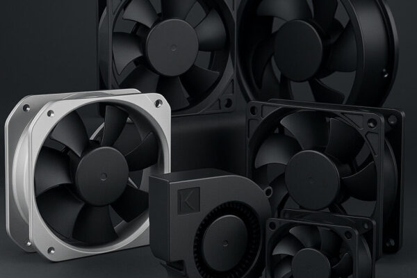
In a shallow vertical envelope, wiring and connectors can interrupt airflow even when the cover appears clear in CAD. Check the complete air path through inlet openings, component channels, filters, and exhaust. Select fans using the required flow at system pressure, then verify the assembled unit under representative operating conditions. Ventilation openings in a product image do not prove adequate cooling for your load.
For auxiliary power, TPS can discuss the appropriate supply class and its mechanical integration. The compact GP-series power-supply guide and PRO-series auxiliary-power guide are related selection resources. A DIN-rail supply must still pass the actual 1U height, mounting, clearance, and thermal checks; a related article is not a fit guarantee.
Define mains, DC, signal, and protective-earth interfaces separately. Include connector retention, conductor bend radius, strain relief, and shielding termination. Powder coating can interrupt electrical contact between panels, so design intentional bonding points where required. Verify continuity and safety functions on the finished assembly rather than relying on metal-to-metal appearance.
Standards, documentation, and reliability
For dimensional review, IEC 60297-3-105:2008 addresses dimensions and design aspects of 1U chassis. Use the applicable rack-interface requirements with the project drawing. Referencing a standard is not evidence that this particular chassis has been certified or tested to every requirement.
The supplied document does not declare an IP rating, shock or vibration test level, load rating, or EMC shielding performance. The shop displays compliance symbols and a RoHS-document link, but the RFQ should request the applicable declaration, its exact product scope, and any supporting evidence. Marks shown on a web page do not establish compliance of the completed electrical assembly.
Reliability depends on the intended environment and manufacturing controls. Specify corrosion exposure, cleaning agents, temperature cycling, transport protection, and finish acceptance where these affect use. At prototype review, check dimensional fit, burrs, threaded interfaces, fastening security, bonding, and thermal behavior. Assign responsibility for each inspection or test before series release.
Move to a larger format when the layout requires it
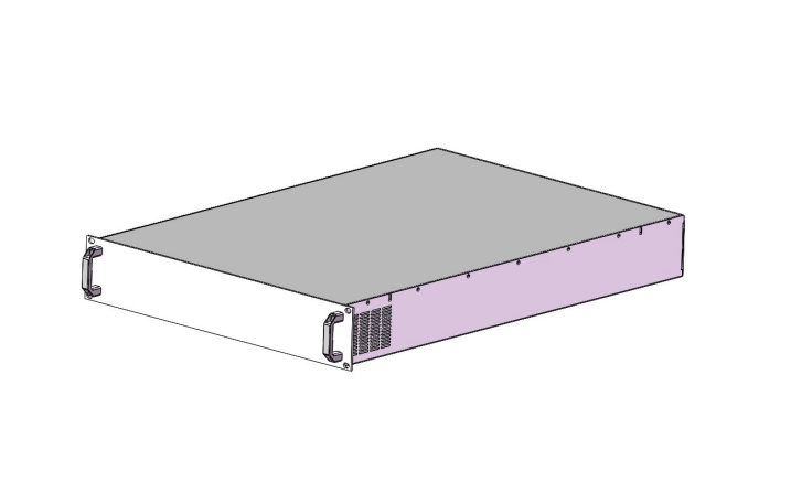
The illustrated enclosure is a 2U alternative, not the 1U product. More height may simplify component layout and service access; each alternative needs its own dimensional and thermal review.
TPS customization and project support
TPS supplies this product class and supports discussions about equivalent enclosure solutions, selection, customization, and integration for global B2B projects. Start with the BJ9900001 1U enclosure listing when the base concept is appropriate; use the TPS chassis and cabinet consultation page to define adaptations or a broader rack solution.
The supplied family document lists sheet steel, aluminum, and galvanized plate without assigning each material to every panel. It specifies powder-coated front, side, top, and bottom plates; powder-coated or nickel-coated rear plates; and colorless oxidation for handles. RAL 7035 or customized color is listed for the front, sides, top, and bottom. Confirm the quoted material stack, finish, and rear-panel treatment.
Other requests can include panel cutouts, connector locations, mounting brackets, threaded hardware, ventilation geometry, labeling, or an integrated subassembly. Submit dimensioned drawings and functional requirements so TPS can review feasibility and quotation scope. These items are subjects for engineering review, not automatically included catalogue features.
For a repeatable OEM platform, agree a prototype approval process before volume orders. Identify the drawing revision, permitted substitutions, inspection points, and approval authority. Where electrical integration is requested, separate enclosure manufacture from wiring, functional testing, and completed-equipment documentation in the quotation.
RFQ checklist and purchasing scope
A useful RFQ describes the assembly and the commercial program together. Send TPS the following information to support a standard-product quotation, an equivalent solution, or a project-specific configuration:
- Mechanical: BJ9900001 reference, required depth, rack interface, component layout, maximum height, loaded mass, support concept, and service clearances.
- Electrical and thermal: operating voltages, connector map, internal losses, ambient conditions, airflow direction, protective-earth strategy, and any insulation requirements.
- Customization: panel drawings, cutouts, mounting features, material requirements, RAL color, surface treatment, labels, and cosmetic acceptance.
- Verification: destination markets, applicable equipment requirements, requested declarations, prototype checks, test responsibilities, and approval criteria.
- Commercial: prototype quantity, batch sizes, annual forecast if available, target delivery date, delivery address and postal code, packaging, and spare-part needs.
Request an explicit bill of supply. The family document lists front plate, side plates, top and bottom plates, and handles; confirm rear-panel inclusion and every accessory because the surface-treatment description alone does not settle the delivery scope. Confirm whether the unit arrives assembled and whether fasteners, internal mounts, fans, rails, or wiring are included.
Stock, production lead time, minimum order quantity, engineering charges, packing method, freight, and quotation validity must be confirmed for the selected configuration. No fixed delivery promise follows from the chassis dimensions. Comparable offers identify assumptions and exceptions clearly, allowing procurement to approve the purchase without leaving essential integration work undefined.
Make the inquiry specific
Attach the component layout and rack constraints, then state quantities, required delivery timing, and the exact enclosure or integration scope.
Request a chassis selection review
Ready to confirm your enclosure? Review the TPS 1U chassis and send the drawing, depth requirement, component list, heat-loss estimate, and quantities through the 19-inch cabinets and chassis inquiry page. TPS can review the base product, suitable alternatives, and the engineering support required for your project.
Frequently asked questions
What are the key dimensions of the TPS 1U chassis?
The supplied family table gives W1 = 482.6 mm, H1 = 43.6 mm, D1 = 666 mm, and D2 = 670.5 mm. The shop separately shows 504.2 mm depth. Obtain the approved drawing for the quoted configuration before integration.
Is the internal usable height 43.6 mm?
No. That value is the external panel height. Covers, sheet thickness, mounting hardware, tolerances, component clearances, and wiring reduce the usable envelope. Request internal dimensions or a CAD model for your layout review.
Can TPS quote a custom 1U rack enclosure?
TPS can review customization and equivalent solutions, including finish, panel machining, mounting features, and integration scope. Provide drawings and quantities; feasibility, pricing, and delivery conditions are confirmed in the offer.
Does the base chassis establish system certification?
No. The chassis document does not provide evidence of completed-equipment approval, an IP rating, or application-specific EMC performance. Request relevant product declarations and define the validation obligations of the final assembly.
What information is needed for a useful quotation?
Send the chassis reference, required depth, component and connector layout, heat losses, support concept, finish, prototype and series quantities, destination, and schedule. These inputs help TPS separate a standard purchase from a modified or integrated project.