

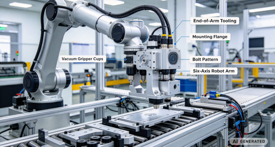
System integrators, panel builders, and procurement teams in robotics integration rarely fail because they lack a robot specification. They lose time—and cycle time—when end-of-arm tooling is too heavy for the robot’s payload rating, when gripper brackets flex under load, or when the mounting flange does not align with the robot wrist bolt pattern within tolerance.
TPS Elektronik’s industrial automation CNC machining services for end-of-arm tooling built to eliminate that risk: precision-machined mounting flanges, topology-optimized structural components, gripper and vacuum manifold machining, and validated tolerances from prototype through series production.
1. What is industrial automation CNC machining for end-of-arm tooling?
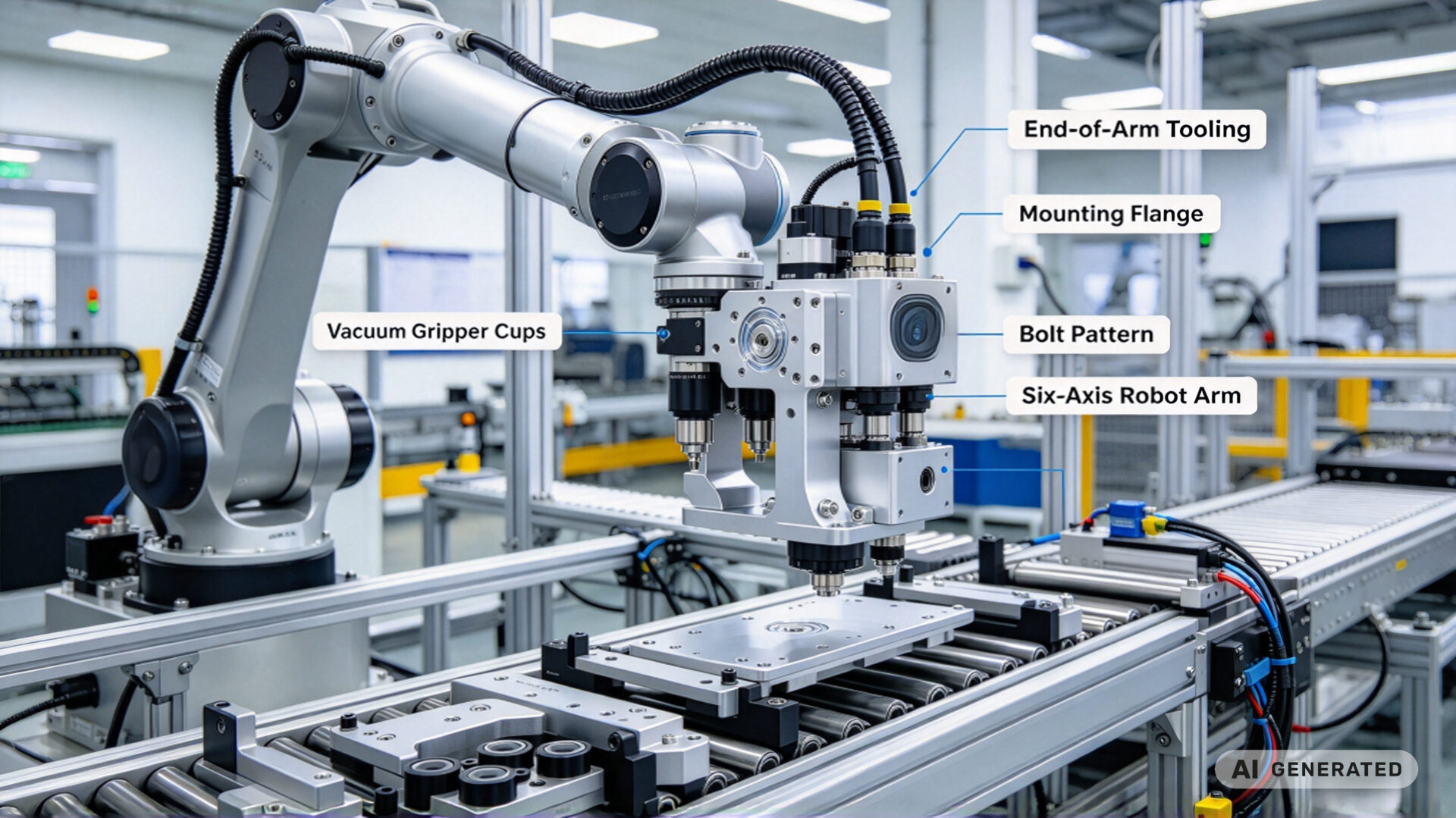
Industrial automation CNC machining for end-of-arm tooling (EOAT) is the precision manufacturing process that converts engineering designs for robot grippers, vacuum cups, mounting flanges, and structural brackets into physical components that attach to a robot wrist and handle the payload. The EOAT is the mechanical interface between the robot and the part being moved—and its mass, stiffness, and geometric accuracy directly determine whether the robotic cell meets its cycle time target.
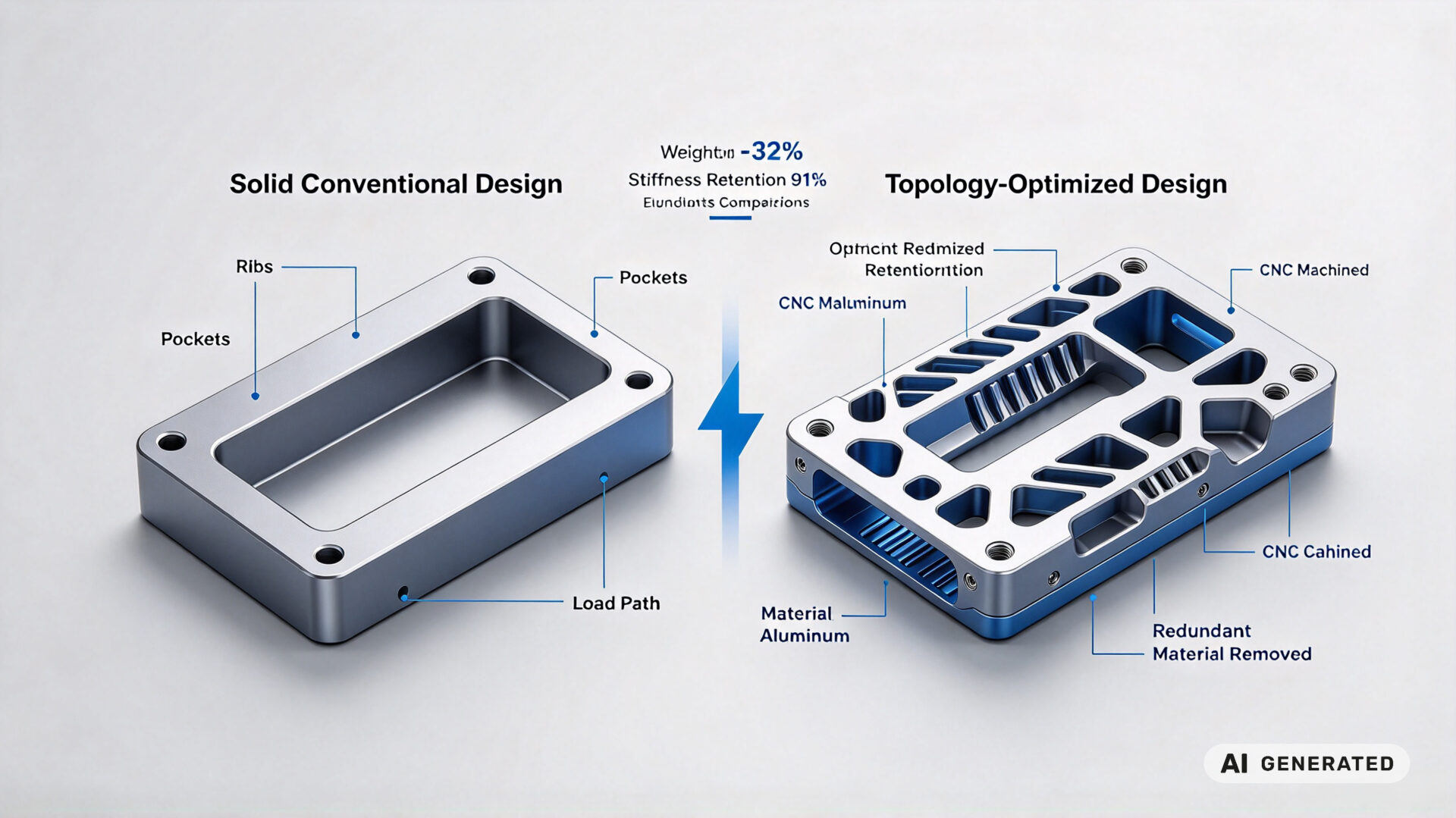
Unlike general-purpose CNC machining, EOAT production governed by three constraints that must satisfied simultaneously: mass minimization, structural stiffness, and mounting accuracy. A bracket that is 20% too heavy reduces the robot’s usable payload. A flange that is 0.1 mm out of position causes the gripper to approach the workpiece at an angle, leading to mis-picks and dropped parts. A structural arm that flexes under acceleration produces positional error at the tool center point.
1.1 Why EOAT machining differs from general CNC work
General CNC machining often evaluated on dimensional accuracy and surface finish alone. EOAT machining adds a third dimension: mass efficiency. Every gram removed from the EOAT is a gram added to the usable payload, and every gram of unnecessary mass increases the inertia that the robot must accelerate and decelerate on every cycle.
This means EOAT machining frequently involves thin-wall sections, pocketed geometries, and topology-optimized structures that would considered impractical in conventional machined parts. A machined aluminum bracket for a fixed installation might have a solid cross-section; the same bracket on a robot arm typically pocketed, ribbed, and chamfered to remove mass while preserving stiffness.
1.2 The component families that make up a typical EOAT
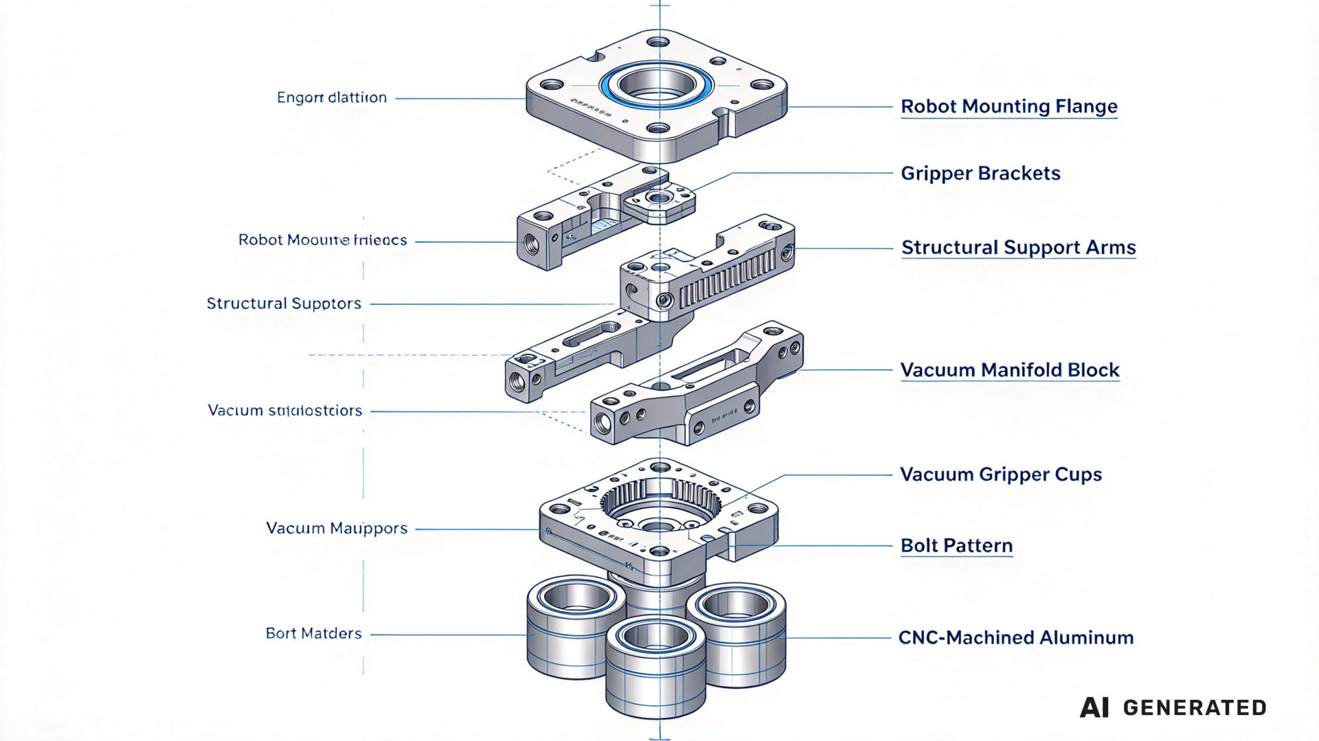
A typical EOAT assembly comprises several distinct CNC-machined component families:
- Robot mounting flange: The interface plate that bolts to the robot wrist. Its bolt pattern must match the robot manufacturer’s specification (ISO 9409-1 for many industrial robots), and its flatness and perpendicularity determine the angular accuracy of the entire tool.
- Structural arms and brackets: The members that position the gripper at the required distance and orientation from the robot wrist. These carry the bending and torsional loads during acceleration.
- Gripper mounting plates: The interface between the structural arm and the gripper itself. These must maintain parallelism between the gripper jaws and the workpiece.
- Vacuum manifold blocks: Machined blocks that distribute vacuum or compressed air to multiple gripper cups, with internal channels that must be leak-tight.
- Custom end effectors: Application-specific jaws, fingers, and contact pads machined to match the workpiece geometry.
TPS’s types of milling machine guide and CNC milling machine options resource document the equipment platform used for these component families.
2. How EOAT mass and stiffness affect payload handling and cycle time
The relationship between EOAT mass and robot performance governed by the robot manufacturer’s payload specification. This specification is not a simple weight limit—it is a limit on the combined mass of the EOAT and the workpiece, at a specified distance from the robot wrist mounting flange.
2.1 The payload math that determines robot selection
Consider a six-axis robot rated for 10 kg payload at its wrist. If the EOAT weighs 4 kg and the workpiece weighs 5 kg, the combined load is 9 kg—within the 10 kg rating. But if the EOAT redesigned with a heavier mounting flange and structural arm, and the new EOAT weighs 6 kg, the combined load becomes 11 kg, exceeding the robot’s rating.
The consequence is not necessarily immediate failure. The robot may still move the load, but at reduced acceleration to avoid exceeding the motor torque limits. This directly increases cycle time. Alternatively, the integrator may need to select a larger, more expensive robot—a decision that cascades through the entire cell design.
The secondary effect is moment of inertia. Payload specifications typically quoted at a specific distance from the wrist flange. If the EOAT shifts the center of mass further from the wrist, the effective moment of inertia increases with the square of the distance. A 1 kg reduction in EOAT mass at 300 mm from the wrist is worth considerably more than 1 kg at 100 mm.
2.2 Inertia, acceleration, and cycle time
Cycle time in a robotic cell determined by the acceleration and deceleration phases of each move, not by the maximum velocity. For a given motor torque, the achievable acceleration is inversely proportional to the total inertia—the sum of the robot arm inertia, the EOAT inertia, and the workpiece inertia. Reducing EOAT inertia therefore directly reduces the torque required for a given acceleration, or allows higher acceleration for the same torque.
Published research on robotic end effector design consistently identifies mass reduction as the primary lever for cycle time improvement. A study in the Journal of Mechanical Design (ASME) on compliant gripper design notes that reducing the moving mass of the end effector is one of the most effective ways to improve the dynamic response of a robotic system.
For integrators, this translates into a design principle: EOAT components should machined to the minimum mass that maintains the required stiffness and fatigue life. This is not a task for a general machining supplier—it requires a partner who understands the load cases and can advise on pocket geometry, rib placement, and material selection.
TPS’s precision CNC machining capabilities configured to support this mass-efficiency design philosophy.
3. TPS CNC machining capabilities for EOAT production
TPS Elektronik operates CNC machining capabilities specifically configured for the precision requirements of robotic end-of-arm tooling, integrated with its EMS and electronic assembly services.
3.1 5-axis machining for complex geometries
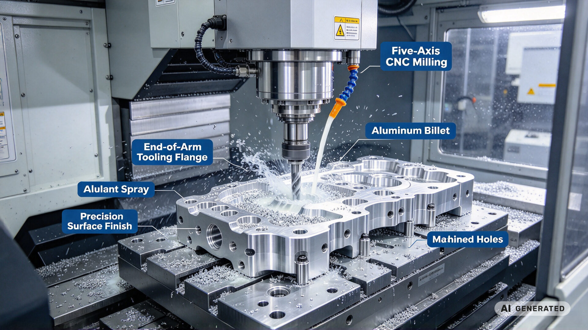
EOAT components frequently require features that cannot produced in a single setup on a 3-axis machine: angled gripper mounting faces, compound-angle bolt patterns, contoured contact surfaces, and internal channels for vacuum or pneumatics. Five-axis simultaneous machining allows these features to produced in a single setup, eliminating the positional error that accumulates across multiple fixtures.
The 5-axis platform at TPS supports:
- Simultaneous 5-axis contouring for complex surfaces
- In-process probing for setup verification and feature measurement
- High-speed spindle operation for aluminum and engineering plastics
- Rigid construction for steel and stainless steel machining
3.2 Tolerances and surface finishes that matter
Not all EOAT features require the same tolerance. The mounting flange bolt pattern and the gripper mounting surface are the two features that drive the overall system accuracy, and these typically specified at ±0.02 mm or tighter. Structural features that do not establish a datum can be held at ±0.1 mm without affecting function.
TPS’s engineering team works with the customer’s design to identify which features are accuracy-critical and which are not—allowing the machining process to focus inspection and process control effort where it matters, without adding cost to non-critical features.
3.3 Material selection: aluminum, steel, and engineering plastics
Material selection for EOAT components involves a trade-off between stiffness, mass, and cost:
- 6061-T6 aluminum: The default choice for most EOAT structural components. It offers a good balance of strength, stiffness, and machinability at low density (2.7 g/cm³). It can anodized for wear resistance and corrosion protection.
- 7075 aluminum: Higher strength than 6061, used for highly loaded gripper fingers and mounting flanges where the additional cost justified.
- Steel (1045, 4140): Used where the EOAT requires impact resistance or where a steel-on-steel interface needed. Three times the density of aluminum, so used sparingly.
- Stainless steel (304, 316L): Used in food processing, pharmaceutical, and cleanroom robotic applications where corrosion resistance is mandatory.
- Engineering plastics (POM, PEEK, UHMW): Used for contact pads, non-marring gripper jaws, and electrical isolation components. PEEK offers high stiffness and temperature resistance; POM is lower cost and easier to machine.
TPS’s precision machining resource documents the material capabilities and process controls for prototype-to-production EOAT manufacturing.
4. Design for manufacturability and robot integration
The most effective way to reduce EOAT cost and lead time is to address manufacturability during the design phase. TPS offers a design-for-manufacturability (DFM) review as part of the quotation process, covering:
- Feature accessibility: Can all required features reached with standard tooling in the minimum number of setups? Compound-angle features that require 5-axis machining add cost, and may avoidable with a small design change.
- Tolerance rationalization: Which features truly need ±0.02 mm, and which can be relaxed? Over-specifying tolerance on non-critical features is one of the most common sources of unnecessary cost.
- Standard component integration: Where possible, using off-the-shelf grippers, flanges, and manifold blocks reduces the number of custom-machined parts and simplifies spare parts management.
- Assembly sequence: The order in which components are assembled affects accessibility for fasteners and cable routing. DFM review can identify assembly issues before the first part machined.
- Robot interface standard: For ISO 9409-1 compliant robot wrists, the mounting flange bolt pattern and pilot diameter standardized. Verifying this at the design stage prevents the costly discovery that the flange does not match the robot after machining.
TPS’s fast RFQ and DFM service provides structured feedback within the quotation cycle, reducing clarification rounds and shortening the path from design to first article.
5. RFQ checklist for EOAT CNC machining
To streamline quotation and evaluation for industrial automation machining of end-of-arm tooling, provide the following information:
- Component list and quantity: Individual part numbers, annual volume, and prototype vs. series split
- 3D CAD models and 2D drawings: STEP or IGES files with tolerance specifications and surface finish requirements
- Material specification: Aluminum alloy grade, steel grade, or engineering plastic, and any heat treatment or surface treatment requirement
- Accuracy-critical features: Which dimensions and datums must held at ±0.02 mm or tighter, and which can be relaxed
- Robot interface details: Robot make and model, wrist bolt pattern standard (ISO 9409-1 or manufacturer-specific), and mounting flange dimensions
- Load and mass targets: Maximum permissible EOAT mass and expected payload weight
- Assembly requirements: Whether TPS should supply individual components or a complete assembled EOAT
- Documentation needs: First article inspection reports, material certificates, dimensional inspection reports
Providing these details reduces clarification cycles during evaluation. TPS’s engineering team can support DFM review, tolerance analysis, and material selection as part of the RFQ process.