For system integrators, panel builders, and engineering‑driven procurement teams, testing a solar inverter not only about measuring efficiency. It also involves simulating the non‑linear output of a photovoltaic array. Which validating the maximum power point tracking (MPPT) algorithm under dynamic conditions. And verifying that the inverter interacts safely with the grid. When a test laboratory uses separate DC sources and AC loads to approximate these functions, the setup is costly, complex, and incapable of sinking power from the inverter during anti‑islanding or grid‑feeding tests.
The TPS high quality bidirectional power module, based on the TPS‑BM75053KTIF‑S platform. Which solves this by integrating a regenerative DC source and load into a single, compact three‑phase unit. It can emulate a solar array on its DC side while simultaneously sinking or sourcing AC power on its grid side. Which enabling complete, energy‑efficient testing of photovoltaic inverters and their grid‑support functions.
Why bidirectional power is critical for solar inverter testing
Testing a grid‑tied photovoltaic inverter requires more than a simple DC power supply. A solar array’s output is a non‑linear I‑V curve that shifts with irradiance and temperature. The inverter’s MPPT algorithm must validated against these dynamic curves to ensure it consistently extracts the maximum available power. On the AC side, the inverter must tested for its ability to synchronize with the grid, ride through voltage and frequency disturbances. And cease operation during an islanding condition. A conventional unidirectional DC source cannot absorb power; it can only supply it. If the inverter under test feeds power back to the source during a grid‑fault simulation, the source may shut down or damaged.
A bidirectional power module eliminates these limitations. It can source power (acting as a PV array simulator) and sink power (acting as a regenerative load). Which enabling complete inverter testing with a single instrument. The TPS‑BM75053KTIF‑S delivers up to 53 kW in either direction, making it suitable for testing both residential and commercial‑scale inverters up to this power level. For a wider overview of the product category, see the TPS bidirectional power module catalog.
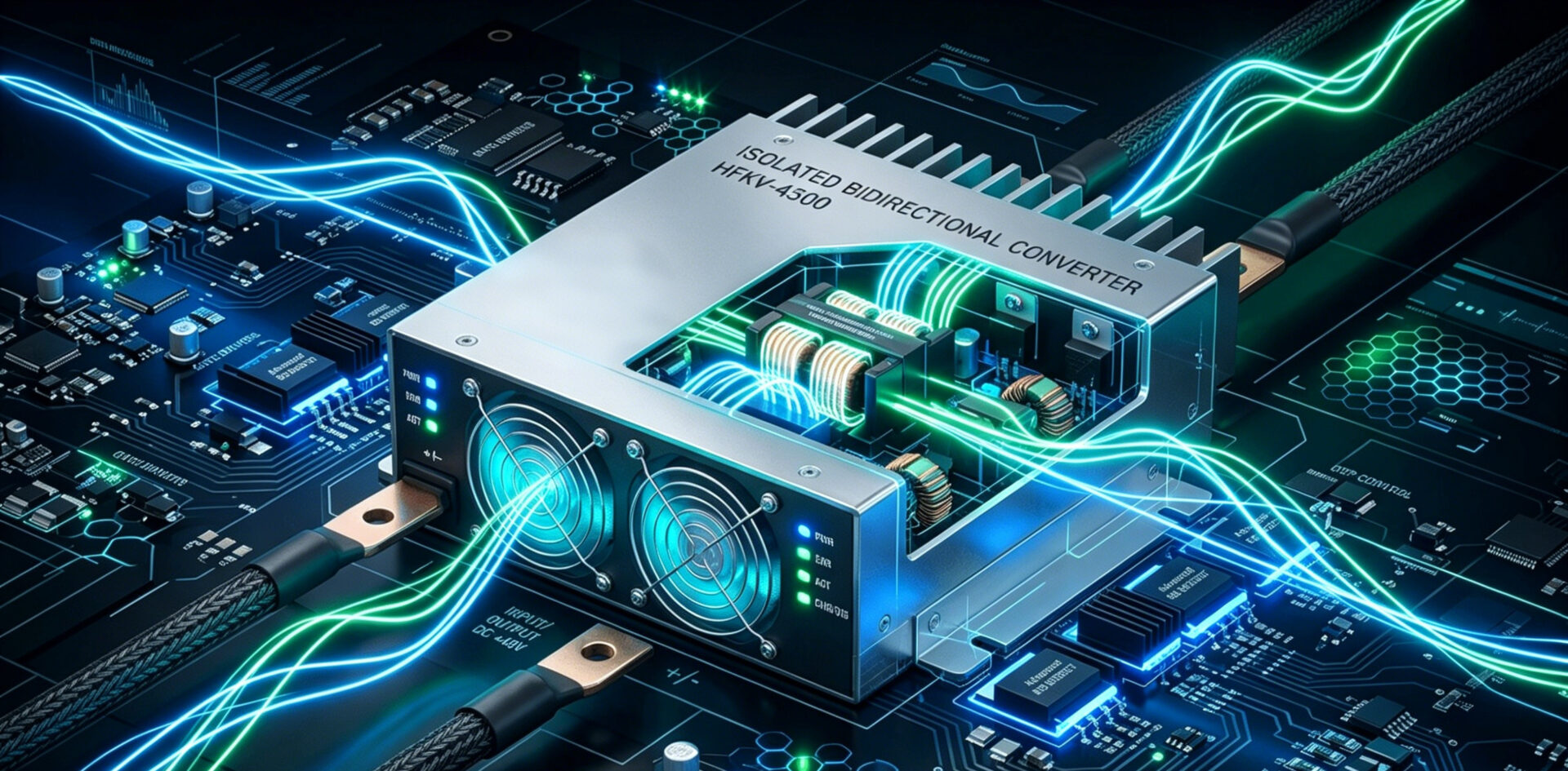
TPS‑BM75053KTIF‑S: a bidirectional power module for PV and grid simulation
The TPS‑BM75053KTIF‑S is a three‑phase AC‑DC bidirectional module rated at 53,000 W. It accepts a wide AC input range of 380/400/415 V AC (±10 %) and delivers a regulated DC output of 750 V DC at up to 70.7 A. In reverse mode, it can convert DC power from a battery or inverter back to the AC grid with an efficiency of 95 %, which enabling energy recycling during burn‑in and aging tests. The module employs soft‑switching technology to reduce switching losses and electromagnetic interference. Which achieving a peak efficiency of 96 % and maintaining a power factor above 0.99 with total harmonic distortion of input current (THDi) below 5 %.
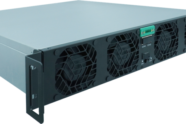
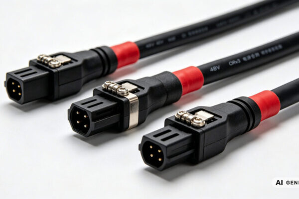
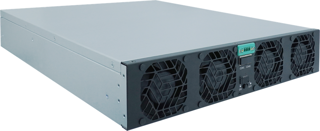
Mechanically, the module measures 435 mm × 86 mm × 600 mm and weighs ≤23 kg, fitting easily into standard 19‑inch rack systems or laboratory benches. Forced air cooling with intelligent fan speed control ensures stable operation even at full load in ambient temperatures up to 45 °C. The front panel provides status LEDs and connectors for AC input and DC output, while the rear panel hosts communication interfaces. Two specific SKU variants—TPS‑DM570T1512KIF and TPS‑DM570T1512KIRF—offer additional current and voltage configurations within the same platform. More product details are available on the TPS product production page.
PV simulation and MPPT testing
A core application of the TPS‑BM75053KTIF‑S is acting as a solar array simulator (SAS). By programming the output I‑V characteristic via its CAN or RS485 interface, the module can replicate the behavior of a specific photovoltaic panel or array under defined irradiance and temperature conditions. This allows test engineers to validate the inverter’s MPPT efficiency according to the procedures defined in EN 50530: the static MPPT efficiency at fixed operating points, and the dynamic MPPT efficiency when the irradiance changes rapidly—simulating passing clouds or partial shading.
The module’s high output voltage accuracy (±0.5 %) and fast transient response (mode switching in <10 ms) ensure that the simulated curve is faithfully reproduced, even when the inverter’s input impedance changes as it tracks the maximum power point. This capability is essential for R&D laboratories and production lines that need to certify inverter performance before deployment. The communication interface enables automated test sequences, with a host computer sweeping through hundreds of I‑V curves while logging the inverter’s response.
Grid integration, anti‑islanding, and LVRT/HVRT testing
On the AC side, the TPS‑BM75053KTIF‑S can simulate grid conditions. When operating as a regenerative load, it absorbs the inverter’s output and returns the energy to the grid with 95 % efficiency. This bi‑directional capability is crucial for testing anti‑islanding protection: the module simulates a grid disconnection while the inverter is feeding power, and the test system monitors whether the inverter ceases to energize the local grid within the required time (typically <2 seconds per IEEE 1547 and VDE‑AR‑N 4105). The module can also emulate low‑voltage ride‑through (LVRT) and high‑voltage ride‑through (HVRT) conditions, verifying that the inverter stays connected during brief grid disturbances as mandated by grid codes worldwide.

Energy efficiency and power recycling
A 53 kW inverter burn‑in test that dissipates the full output as heat in a resistive load would consume over 460,000 kWh annually and require substantial air conditioning to remove the waste heat. By using the TPS‑BM75053KTIF‑S in regenerative mode, over 95 % of this energy is returned to the grid, drastically reducing operating costs and carbon footprint. This feature also makes the module ideal for battery PACK aging and energy recyclable power aging applications, where charge‑discharge cycles are performed with minimal net energy consumption. The module’s soft‑switching technology contributes to this high efficiency by reducing switching losses at the power semiconductors.
Modular design and scalability
The TPS‑BM75053KTIF‑S employs a modular architecture, allowing multiple units to be paralleled on both the AC and DC sides for higher power requirements. This scalability enables test systems to grow from a single‑module 53 kW station to a multi‑module 500 kW+ facility by simply adding modules and synchronizing them via the CAN bus. The master‑slave communication protocol ensures balanced current sharing and coordinated operation, while the modular design simplifies maintenance—a single module can be replaced without shutting down the entire system.
Communication, control, and system integration
Integration into automated test equipment (ATE) is essential for production environments. The module features built‑in CAN and RS485 interfaces as standard, supporting SCPI‑compatible command sets that enable control from LabVIEW, Python, MATLAB, or any custom test executive. Key parameters—voltage, current, power, and protection limits—can be set and read in real time, enabling closed‑loop test automation. The module also provides isolated digital I/O for safety interlocks and external emergency stop integration. For more technical content on integrating such devices, explore the TPS blog content.
Compliance and certifications: IEC 62477‑1, EN 55032, UL/CE/TUV
Safety and electromagnetic compatibility are critical for equipment operating in test laboratories and production floors. The TPS‑BM75053KTIF‑S is compliant with IEC 62477‑1, the international safety standard for power electronic converter systems, and EN 55032 Class A for electromagnetic emissions. It holds UL, CE, and TUV certifications, ensuring that it meets the regulatory requirements for deployment in North America, Europe, and international markets. The module’s design also incorporates comprehensive protection functions: over‑voltage, over‑current, over‑temperature, and short‑circuit protection, all with automatic recovery.
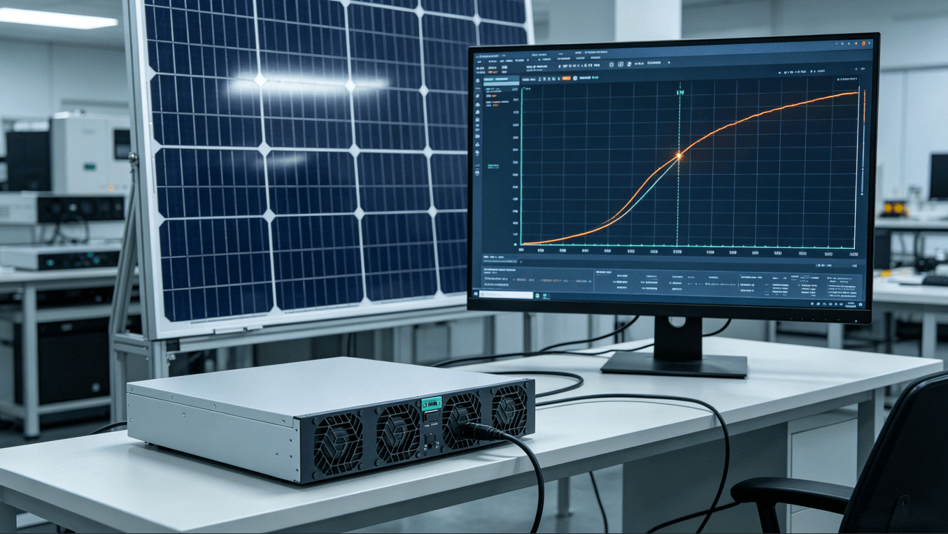
Application scenarios: PV inverter test, battery aging, microgrid simulation
- Photovoltaic inverter testing: Complete MPPT efficiency validation, anti‑islanding, LVRT/HVRT, and grid‑code compliance testing.
- Battery PACK aging and formation: Bidirectional charging/discharging cycles with energy recovery, reducing electricity costs.
- Smart grid and microgrid simulation: Emulating distributed energy resources and testing energy management systems.
- DC microgrid and energy storage test beds: Providing a controllable DC bus with both source and sink capability.
RFQ checklist for bidirectional power modules
- Power level: Required DC output power (e.g., 53 kW) and whether future scalability is needed.
- Voltage and current range: Nominal DC voltage (e.g., 750 V) and current, plus any specific AC input voltage.
- Application mode: PV simulation, battery cycling, grid integration, or a combination.
- Communication interface: CAN, RS485, or any additional fieldbus requirements.
- Certifications: Required marks (UL, CE, TUV) and applicable standards (IEC 62477‑1, EN 55032).
- Quantities and schedule: Prototype, pilot, and series volumes.
Frequently Asked Questions
Can the TPS‑BM75053KTIF‑S simulate a specific solar panel model?
Yes, by programming the I‑V curve parameters via the CAN/RS485 interface, the module can emulate the electrical behavior of any common photovoltaic panel technology.
What is the energy recovery efficiency of the module?
The module achieves up to 95 % efficiency in regenerative (DC‑to‑AC) mode, returning the absorbed energy to the grid with minimal losses.
How many modules can be connected in parallel?
Multiple modules can be paralleled to scale power into the hundreds of kilowatts, with synchronized control via the CAN bus.
Where can I find the complete product specifications?
Visit the TPS high quality bidirectional power module catalog or the product production page for datasheets and application notes.