

For system integrators, panel builders, and engineering-driven procurement teams, selecting a current probe for switch mode power supply design is not only about bandwidth.
It also involves dynamic range, DC accuracy, safety ratings, and whether the probe can capture the transient events—inrush current, inductor ripple, switching edges—that determine whether the power supply passes verification or fails in the field.
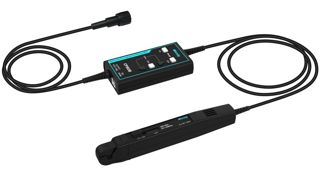
The Micsig CP503B is a high-frequency AC/DC current probe with DC~50MHz bandwidth, dual 6A/30A ranges, and ±1% typical DC accuracy. It features a standard BNC interface, auto-degaussing, one-touch zero calibration, and CAT I 300V safety compliance.
Typical applications include switching power supply design, motor driver development, inverter testing, and semiconductor device characterization.
1. What a power supply current probe is (and why shunt resistors fall short)
A power supply current probe is a clamp-type measurement instrument that senses the magnetic field surrounding a conductor and converts it to a voltage signal proportional to the current flowing through that conductor. Unlike shunt-resistor-based measurement, a clamp probe requires no circuit interruption and introduces no insertion impedance.
In SMPS design verification, the two dominant current measurement techniques are shunt resistors and current probes. Tektronix application note 51W-60161 describes both approaches, noting that shunt resistors provide good accuracy but introduce power dissipation that increases with the square of the current, add inductive reactance to the circuit, and require breaking the circuit for insertion. Clamp-type current probes, by contrast, are recommended when input and output cables are accessible—the probe simply clamps around the conductor without modifying the circuit under test.
The practical limitation of shunt resistors in modern SMPS design is becoming more acute. As switching frequencies increase and power densities rise, the physical space available for a shunt resistor shrinks, and the parasitic inductance of the resistor itself begins to distort the very waveform it is intended to measure. A current probe for power supply design eliminates these constraints.
2. Inrush current analysis: capturing the transient that trips breakers
Inrush current is the surge that occurs when a power supply is first energized—the input capacitors charge rapidly, drawing a current pulse that can exceed normal operating current by 10 to 100 times. For switching power supplies that rectify incoming AC directly without an input transformer, surge currents of 40 to 100 times normal operating current are common, typically lasting several AC line cycles.
Capturing this transient accurately is essential for three reasons: selecting the correct fuse or circuit breaker rating, verifying that the soft-start circuit functions as designed, and ensuring that multiple power supplies in the same system do not trip the upstream protection when energized simultaneously.
The challenge is that inrush events last only milliseconds. Standard current probes often saturate and provide misleadingly low readings when currents exceed about 12 to 14 times their rated capacity. A SMPS inrush current probe must have sufficient peak current headroom and fast enough response to capture the full amplitude without clipping.
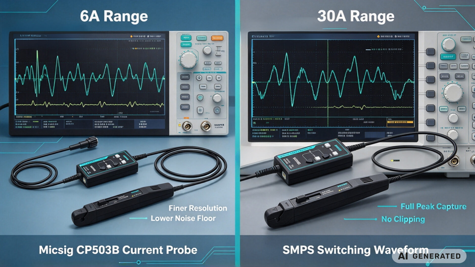
The Micsig CP503B addresses this with a 30A peak range (50mA~30Apk) and a 6A range (20mA~6Apk) for lower-amplitude detail. The overload indicator flashes when the input exceeds the selected range, preventing the user from recording a clipped waveform without knowing it—a critical safeguard when the consequence of an underreported inrush current is a mis-rated circuit breaker.
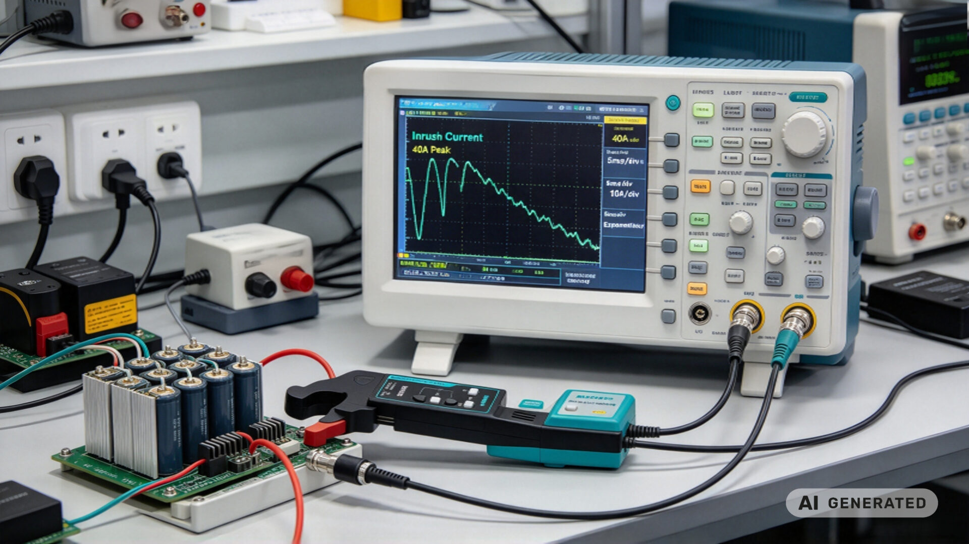
For a detailed methodological reference on inrush characterization, Keysight’s application note on capturing inrush current with digitizing multimeters demonstrates the trigger setup and zoom analysis techniques used to resolve peak overshoot and settling behavior.
3. Ripple current measurement: verifying inductor and capacitor behavior
In switch mode power supply design, ripple current flows through the inductor and output capacitor as the switching element alternately stores and releases energy. The magnitude of this ripple current determines the inductor’s saturation margin, the capacitor’s thermal stress, and the output voltage ripple that appears at the load.
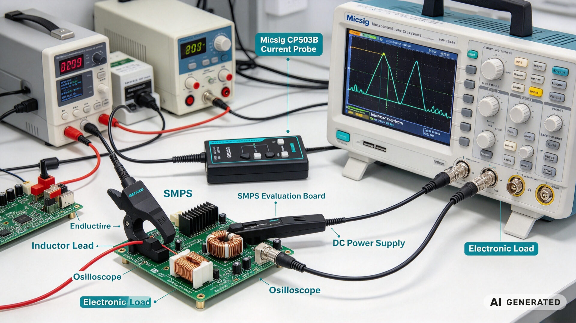
Measuring inductor ripple current is a standard verification step in SMPS evaluation. The current probe is clamped around the inductor lead, and the oscilloscope displays the triangular current waveform. From this waveform, the engineer confirms that the ripple magnitude matches the calculated value and that the inductor is not entering saturation—a condition that would cause a sudden increase in ripple current and potential thermal failure.
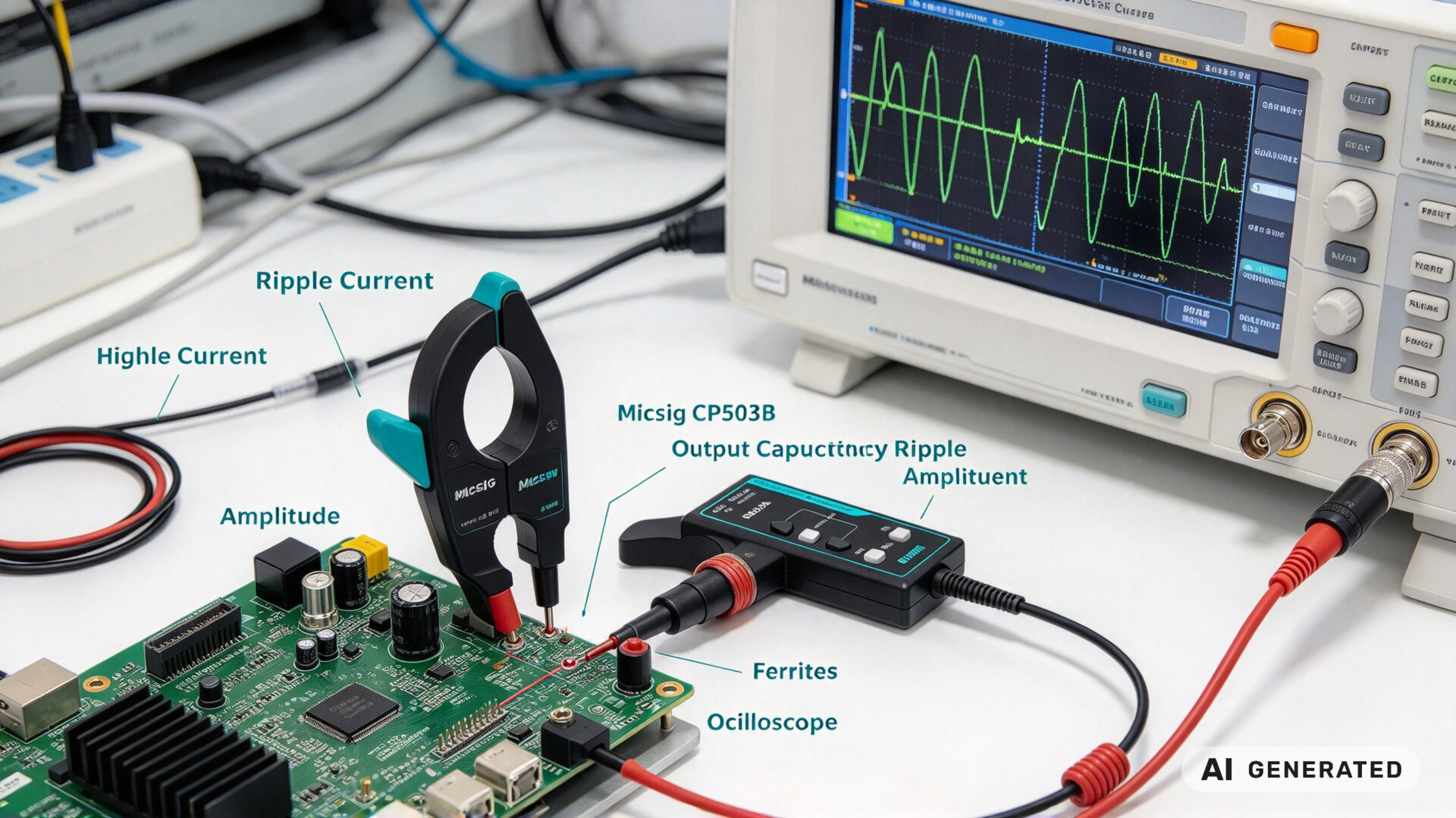
For output capacitor ripple current, the measurement is equally important but more challenging. The switch mode power supply ripple current flowing through the output capacitor has a high-frequency content that requires adequate probe bandwidth to capture without attenuation. A probe with insufficient bandwidth will underreport the ripple amplitude, leading to an incorrect assessment of capacitor stress and potential field failures.
The CP503B’s DC~50MHz bandwidth and ≤1.4mA RMS noise floor (30A range, 20MHz bandwidth) provide the resolution needed to distinguish the ripple current from measurement system noise. For designs using wide-bandgap semiconductors such as SiC or GaN, where switching edges can be as fast as 4ns, a minimum bandwidth of approximately 87.5MHz is required to capture the switching transition accurately—the CP503B’s 50MHz bandwidth covers the fundamental and harmonics up to 20MHz and beyond, making it suitable for the majority of industrial SMPS designs.
4. Bandwidth and accuracy: matching the probe to the SMPS switching frequency
The relationship between probe bandwidth and measurement accuracy follows a simple rule: to measure a signal with rise time t, the measurement system bandwidth must be at least 0.35/t. For a typical industrial SMPS switching at 100kHz with 20ns switching edges, the required bandwidth is 17.5MHz. For a GaN-based design with 4ns edges, the requirement rises to 87.5MHz.
The CP503B’s 50MHz bandwidth covers the majority of industrial and consumer SMPS designs. Its rise time specification of ≤7ns ensures that the probe does not itself become the limiting factor in the measurement chain for switching frequencies up to approximately 50MHz.
Physical Characteristics
| Parameter | Specification |
|---|---|
| Model | Micsig CP503B |
| Bandwidth | DC~50MHz |
| Rise time | ≤7ns |
| Current ranges | 6A (20mA~6Apk) / 30A (50mA~30Apk) |
| Output sensitivity | 1V/2A (6A range) / 1V/10A (30A range) |
| Max conductor diameter | 5mm |
| Power supply | DC 5V 3A (USB-powered) |
| Interface | Standard BNC |
The dual-range architecture allows the user to select the 6A range for low-current measurements (gate drive currents, standby currents) with ±10mA resolution, or the 30A range for full-load and inrush measurements with ±50mA resolution. Both ranges maintain the same ±1% accuracy specification.
5. Mechanical and safety considerations for bench integration
The CP503B is designed for bench and field use. Its compact, lightweight form factor and USB-powered operation (DC 5V 3A) eliminate the need for a separate power supply, simplifying setup in laboratory or field environments.
The auto-degaussing function is particularly valuable in SMPS measurement workflows. Magnetic cores in current probes retain residual magnetization from previous measurements, which introduces a DC offset error. The CP503B performs degaussing and zero calibration automatically when the “Zero” button is pressed—a single action that replaces the manual degaussing procedure required by some competing probes.
The CAT I 300V safety rating is appropriate for the low-voltage, isolated secondary-side measurements that dominate SMPS design verification. The probe is not intended for direct connection to mains voltages or high-energy circuits; for primary-side measurements or AC input analysis, a higher CAT-rated probe is required.
For system integrators and panel builders, the BNC interface ensures compatibility with all standard oscilloscopes, and the probe’s automatic overload indication prevents inadvertent damage when measurements exceed the selected range.
6. Product specifications
| Parameter | CP503B | Typical Generic Probe |
|---|---|---|
| Bandwidth | DC~50MHz | DC~10MHz |
| Rise time | ≤7ns | ≥35ns |
| Current ranges | 6A / 30A (dual) | Single range |
| DC accuracy | ±1% + 10mA / 50mA | ±3% or worse |
| Noise floor | ≤1.4mA RMS | Often unspecified |
| Auto-degaussing | Yes | Manual or none |
| Overload indicator | Flashing light | Often none |
| Safety rating | CAT I 300V | Varies |
| Power | USB DC 5V 3A | AC adapter or battery |
7. RFQ checklist
To streamline quotation and evaluation for a power supply current probe, provide the following information:
- Application type: SMPS design, motor drive, inverter, or general power electronics
- Current range required: Maximum continuous and peak current to be measured
- Switching frequency and edge rate: For bandwidth requirement calculation
- Oscilloscope interface: BNC, and whether the oscilloscope has probe power supply compatibility
- Safety environment: Measurement category required (CAT I, II, III)
- Portability requirement: Bench-only or field use
- Quantity: Single unit, multi-unit purchase, or series procurement
Providing these details reduces clarification cycles during evaluation. TPS’s engineering team can support bandwidth calculation, range selection, and safety rating assessment as part of the RFQ process.
8. FAQ
What bandwidth does a current probe need for SMPS design?
The required bandwidth depends on the switching frequency and edge rate. For a typical industrial SMPS with 100kHz switching and 20ns edges, a minimum bandwidth of 17.5MHz is required. The CP503B’s 50MHz bandwidth provides margin for designs with faster edges and covers the fundamental and harmonics up to 20MHz and beyond.
Can the CP503B measure inrush current without saturating?
Yes. The 30A range (50mA~30Apk) captures inrush events with peak current up to 30A. The maximum current input is 30Apk, 60Apk-pk, or 21.21Arms. The overload indicator flashes if the input exceeds the selected range, preventing inadvertent recording of a clipped waveform.
How does auto-degaussing improve measurement accuracy?
Magnetic cores in current probes retain residual magnetization from previous measurements, which introduces a DC offset error. Auto-degaussing on the “Zero” button removes this residual magnetization and calibrates the zero point simultaneously, ensuring accurate DC and low-frequency measurements.
Is the CP503B suitable for primary-side measurements?
No. The probe is rated CAT I 300V, which is appropriate for low-voltage, isolated secondary-side measurements. For primary-side or mains-connected measurements, a higher CAT-rated probe with galvanic isolation is required. Contact TPS for a recommendation based on your measurement environment.
Does the CP503B work with any oscilloscope?
Yes. The standard BNC interface ensures compatibility with any oscilloscope that has a BNC input. The probe is powered separately via USB (DC 5V 3A) and does not require probe power from the oscilloscope.