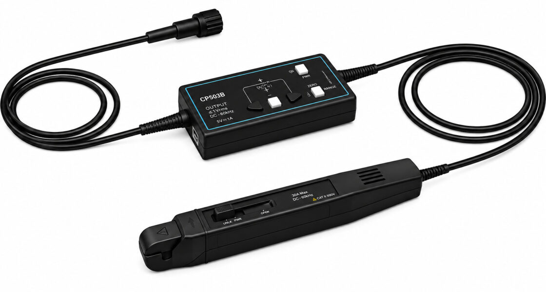
When designing an Electric vehicle transportation design or a Switching power supply design, engineers often face a critical challenge: how to accurately measure fast, high-frequency transient currents. Whether you are dealing with MOSFET switching spikes, inductor inrush currents, or PWM ripple, the right oscilloscope probe is essential. A standard current probe may not provide the bandwidth or sensitivity needed. In many cases, a differential probe or a hi voltage solution combined with a high voltage probe is used for voltage measurements, but for current, you need a dedicated test probe such as a current clamp probe for oscilloscope. But what is the best approach? Understanding oscilloscope what is its role in power electronics leads us to the scope current probe. Specifically, a High Frequency AC DC Current Probe is the ideal tool for these applications. This article will guide you through the challenges of measuring high-frequency transient currents, how to measure high frequency current signal accurately, how to measure surge current during startup, and how to solve low frequency probe distortion.
The Core Problem: Bandwidth Limitation and Low-Frequency Probe Distortion
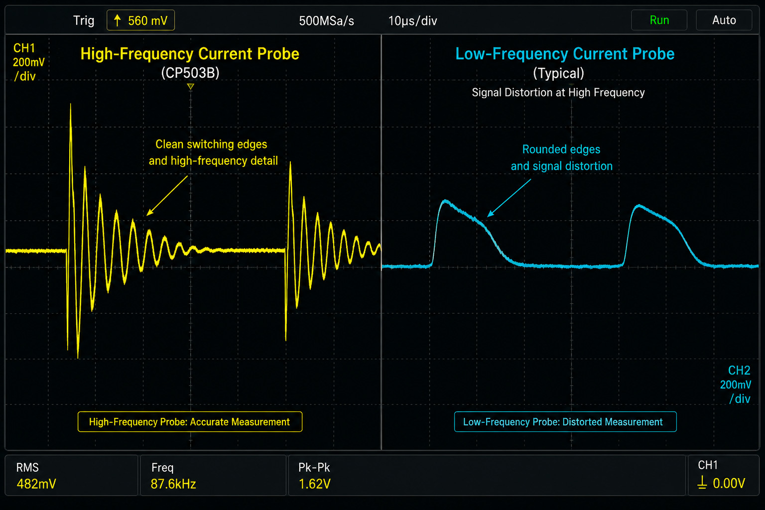
Many engineers start with a general-purpose current clamp probe for oscilloscope that works well for 50/60 Hz power lines or low-speed motor currents. However, when faced with fast switching edges (rise times < 50 ns) found in modern GaN or SiC power stages, such probes produce severe waveform distortion. This is because their bandwidth is often limited to a few hundred kHz. As a result, you cannot measure high frequency current signal properly. The waveform appears rounded, delayed, or completely reshaped. This low frequency probe distortion leads to incorrect calculations of switching losses, false conclusions about EMI, and ultimately unreliable designs. To solve low frequency probe distortion, you need a probe with at least 50 MHz to 100 MHz bandwidth, fast rise time, and flat response over the frequency range of interest. A High Frequency AC DC Current Probe like those used in professional power electronics labs achieves exactly that.
Dual Range Selection – Measuring Both Large Surge and Small Ripple
One of the most practical features in modern probes is the Dual range selection current probe. Power electronics often require measuring a wide dynamic range: from tens of milliamps of idle current to tens of amps of peak surge current. A single fixed gain would either saturate on large signals or have insufficient sensitivity for small currents. With dual ranges (e.g., 6A and 30A), you can measure low current easily in the sensitive range (e.g., 1V/2A output) and then switch to the high range (e.g., 1V/10A) for capturing inrush or overload events. This capability directly helps reduce measurement error because the signal-to-noise ratio is optimized for each amplitude. Key features include:
- Dual range selection current probe: 6A (high sensitivity) and 30A (high current) ranges, selectable by a front-panel button.
- Output sensitivity: 1V/2A (6A range) and 1V/10A (30A range), compatible with any 1MΩ BNC input oscilloscope.
- Ability to measure surge current up to 30A peak (60A peak-to-peak) without saturation.
- Low current resolution: down to 20 mA in 6A range, enabling idle current monitoring in standby modes.
Degaussing and Automatic Zero Setting – Eliminate DC Offset and Remanence
Current probes that use a Hall effect sensor (for DC) and a coil (for AC) suffer from two common artifacts: remanent magnetism (core memory) and thermal drift of the Hall element. This results in a non-zero output even when no current flows, causing measurement errors especially at low currents. A Degaussing current probe solves the first problem by applying a decaying alternating magnetic field to demagnetize the core. A Automatic Zero setting current probe then compensates for any remaining offset. With a single press of the “Zero” button, the probe performs both degaussing and auto-zero, ensuring accuracy before each critical measurement. This is indispensable when you need to reduce measurement error to ±1% or better. Key features:
- Degaussing current probe with built-in degaussing coil – no external degausser required.
- Automatic Zero setting current probe – one-button operation, LED indicator shows zeroing complete.
- DC accuracy: ±1% ±10 mA (6A range) / ±1% ±50 mA (30A range) typical.
- Noise: ≤ 1.4 mA RMS (bandwidth limited to 20 MHz) – essential for clean low-current readings.
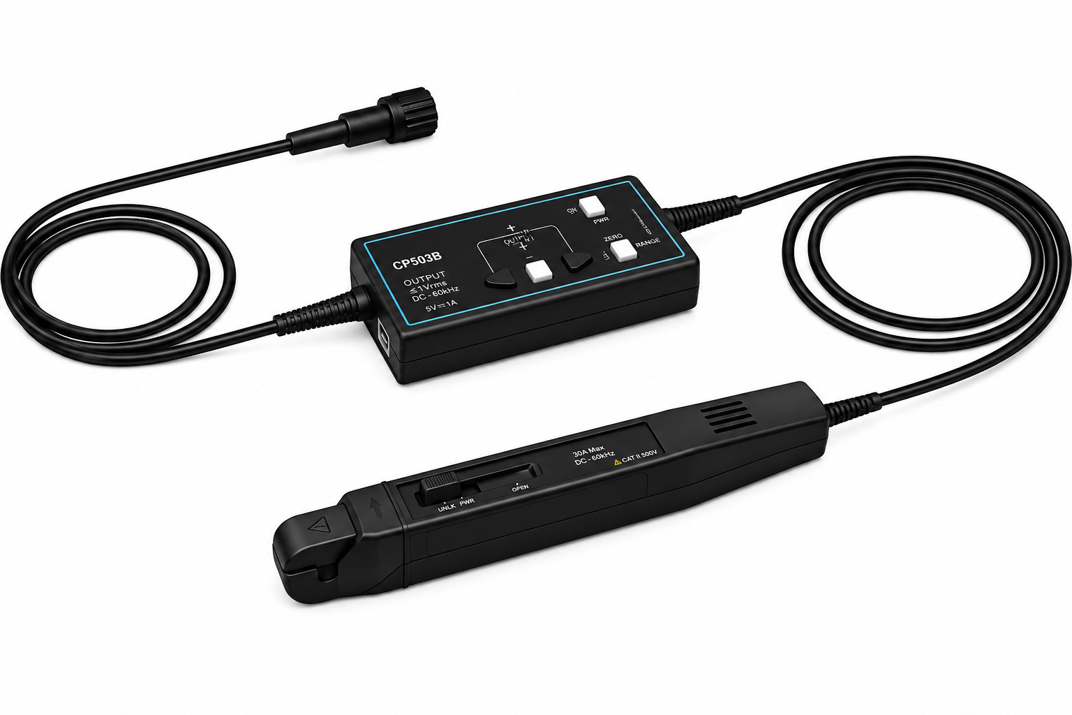
BNC Interface and Universal Compatibility
Unlike specialized probes that require proprietary connectors or external power supplies, a BNC interface current probe offers universal compatibility. Any oscilloscope with a standard BNC input (which is nearly all scopes) can directly accept the probe’s output. Furthermore, the probe is powered by a DC 5V/3A supply (often via USB or an included adapter), so there is no need for a dedicated probe interface. When you ask oscilloscope what is its most common input interface – the answer is BNC. Therefore, using a BNC interface current probe ensures that you can quickly move between different oscilloscopes in the lab. This feature is especially valuable in Experiment of electronic engineering and Power electronics experimental design environments where multiple test stations exist. Key benefits:
- BNC interface current probe – plug-and-play with any 1 MΩ oscilloscope input.
- Low output impedance (50Ω typical) and short delay (<30 ns) ensures accurate timing alignment with voltage probes.
- No calibration box or complex setup – simply connect, degauss/zero, and measure.
- Overload indicator (flashing LED) warns when input current exceeds the selected range.
Applications Across Industries and Research Fields
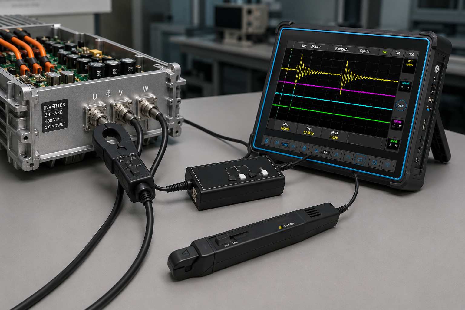
With the capabilities described above, a High Frequency AC DC Current Probe becomes an essential tool across many domains. In Electric vehicle transportation design, it captures motor phase currents and DC-link ripple. In Switching power supply design, it measures inductor currents and switch node transients. Semiconductor devices design benefits from accurate characterization of dynamic on-resistance and switching loss. Avionics design requires reliable current monitoring in harsh electrical environments. Inverter design and Transformer design both need wide-bandwidth current probes to analyze core saturation and leakage inductance effects. Electronic ballast design for lighting relies on high-frequency current measurement to ensure proper lamp striking and steady-state operation. Industrial Control design and Consumer Electronics design use these probes for power integrity and standby power optimization. Engine driven design (e.g., hybrid vehicles) and Electric drive experimental design rely on accurate current feedback for control loop tuning. The probe is also a standard tool in university Experiment of electronic engineering courses and Power electronics experimental design labs.
Specification Summary (Example: 50 MHz / 100 MHz Class Probe)
| Parameter | Value |
|---|---|
| Bandwidth (–3dB) | 50 MHz / 100 MHz |
| Rise Time | ≤7 ns / ≤3.5 ns |
| Ranges | 6A (high sensitivity), 30A (high current) |
| Output Sensitivity | 1V/2A (6A), 1V/10A (30A) |
| DC Accuracy | ±1% ±10 mA (6A), ±1% ±50 mA (30A) |
| Delay Time | <30 ns (both ranges) |
| Max Continuous Current | 30A peak, 60A p-p, 21.21A RMS |
| Max Working Voltage (CAT I) | 300V (floating / to ground) |
| Noise (20 MHz BW, 30A range) | ≤1.4 mA RMS |
| Conductor Diameter | 5 mm max |
| Power Supply | DC 5V / 3A |
| Interface | BNC (1 MΩ oscilloscope input) |
How to Reduce Measurement Error in Practice
Even with a high-performance probe, correct usage is key to reduce measurement error. Follow these steps: (1) Always degauss and auto-zero the probe before each measurement, especially after changing range or when the probe has been exposed to large currents. (2) Keep the probe head closed and centered on the conductor to avoid position-dependent errors. (3) Use the lowest range that does not overload, because the Dual range selection current probe gives better signal-to-noise ratio in the lower range. (4) Consider the probe’s delay (<30 ns) when comparing with a voltage probe – most oscilloscopes have deskew functions to reduce measurement error in power loss calculations. (5) For very low currents (<100 mA), use the 6A range and enable bandwidth limiting (20 MHz) on the oscilloscope to reduce high-frequency noise. This allows you to measure low current easily with high confidence.
Conclusion: A Must-Have Tool for Modern Power Electronics
In summary, capturing high-frequency transient currents in Electric vehicle transportation design and Switching power supply design demands a specialized oscilloscope probe. A standard current probe or current clamp probe for oscilloscope with limited bandwidth will produce low frequency probe distortion and cannot measure high frequency current signal accurately. By contrast, a High Frequency AC DC Current Probe with Dual range selection current probe, Degaussing current probe, Automatic Zero setting current probe, and BNC interface current probe features solves these problems. It enables you to measure surge current during startup, measure low current easily in standby modes, and reduce measurement error to within ±1%. Whether you are involved in Experiment of electronic engineering, Semiconductor devices design, Avionics design, Inverter design, Transformer design, Electronic ballast design, Industrial Control design, Consumer Electronics design, Engine driven design, Power electronics experimental design, or Electric drive experimental design, this probe will become an indispensable part of your test bench. And for those looking beyond existing products, we have already developed our own self-designed scope current probe with comparable or superior performance – ready to support your most demanding applications.


