Plant engineers, maintenance managers, and procurement teams rarely fail because they lack a maintenance budget. They lose time—and production—when a critical medium‑voltage power cable fails unexpectedly. Or a distribution transformer develops a winding short that could have been predicted months earlier. The resulting unplanned outage can cost a factory hundreds of thousands of dollars in lost output. While the emergency repair itself may rushed and expensive. In most cases, the root cause is a gradual degradation of insulation that went undetected because it never measured.
TPS Elektronik’s electrical insulation resistance test service, delivered through its accredited EMC and electrical safety laboratory. Which designed to detect these hidden threats. By applying precision diagnostic testing—including spot readings, Dielectric Absorption Ratio (DAR), and Polarization Index (PI) evaluation. TPS provides the quantitative condition data that enables maintenance teams to make informed decisions about repair, replacement, or continued safe operation of critical power assets.
1. Why insulation resistance testing is fundamental to industrial asset management
Industrial power cables, switchgear, and transformers are long‑term capital investments, often expected to operate reliably for 20 to 40 years. Over that lifespan, the insulation systems—comprising polymers, oil‑impregnated paper, and epoxy resins. Which subjected to thermal stress, moisture ingress, contamination, and partial discharge. Each of these mechanisms gradually reduces the dielectric strength of the insulation. Which increasing the risk of a phase‑to‑phase or phase‑to‑ground fault. When a fault occurs, the result is not just a repair bill. It is the unplanned downtime of an entire production line.
Industrial power cable testing using insulation resistance measurement is one of the most effective non‑destructive diagnostic tools available. It provides a direct, quantitative assessment of insulation integrity, detecting problems such as water treeing in XLPE cables. Which moisture absorption in paper‑insulated lead‑covered (PILC) cables, and surface contamination on switchgear busbars. When performed regularly and the results trended over time, insulation resistance testing becomes the cornerstone of a predictive maintenance program that can extend asset life and prevent catastrophic failures. For a broader perspective on how electrical safety testing integrates into compliance frameworks, see our resource on EMC and electrical safety testing for compliance and reliability.
2. Insulation resistance test methods: spot test, DAR, and polarization index
Insulation resistance testing is not a single measurement. Depending on the asset type, voltage class, and the diagnostic information required, different test methods are applied. The three primary methods are the spot reading test, the Dielectric Absorption Ratio (DAR) test, and the Polarization Index (PI) test. Each provides a different perspective on insulation condition.
2.1 Spot reading test
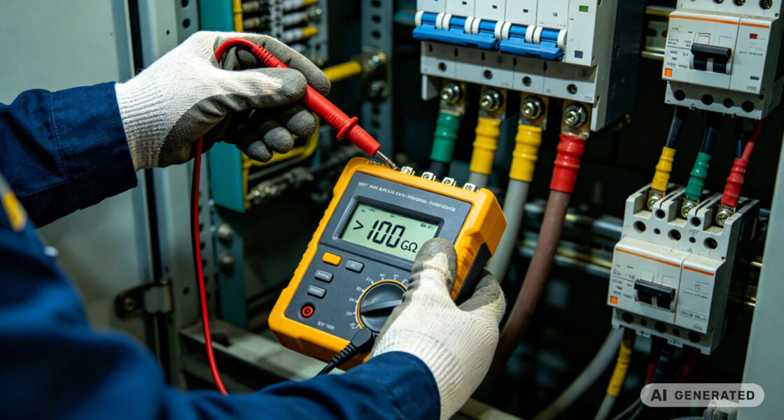
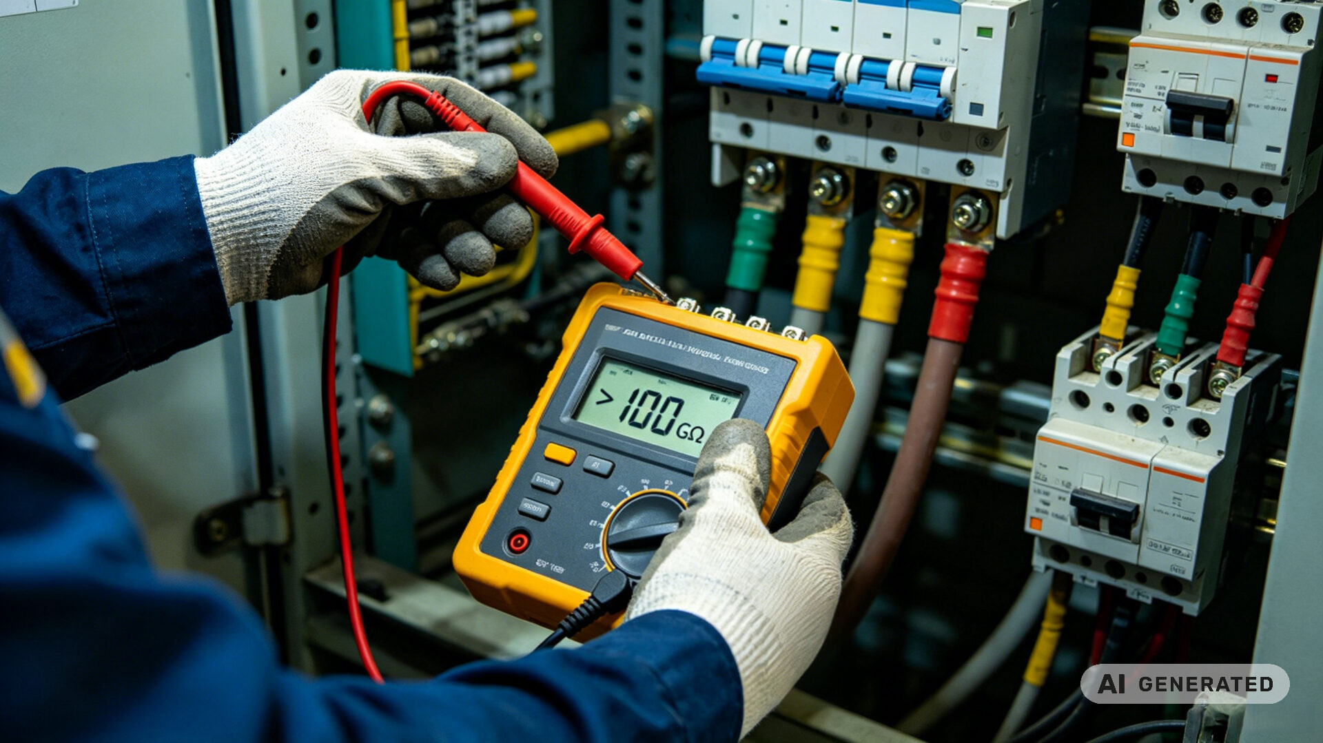
The spot reading test is the simplest form of insulation resistance measurement. A DC test voltage—typically 500 V, 1000 V, 2500 V, or 5000 V, depending on the asset’s rated voltage. It applied for a short duration (usually 60 seconds), and the resistance is recorded. The resulting value compared against the minimum acceptable value recommended by the relevant standard (such as IEEE 43) or the equipment manufacturer. While quick and useful for a pass/fail assessment, the spot test provides limited insight into the condition of the insulation. Because it does not capture the time‑dependent behavior of the dielectric material.
2.2 Dielectric Absorption Ratio (DAR)
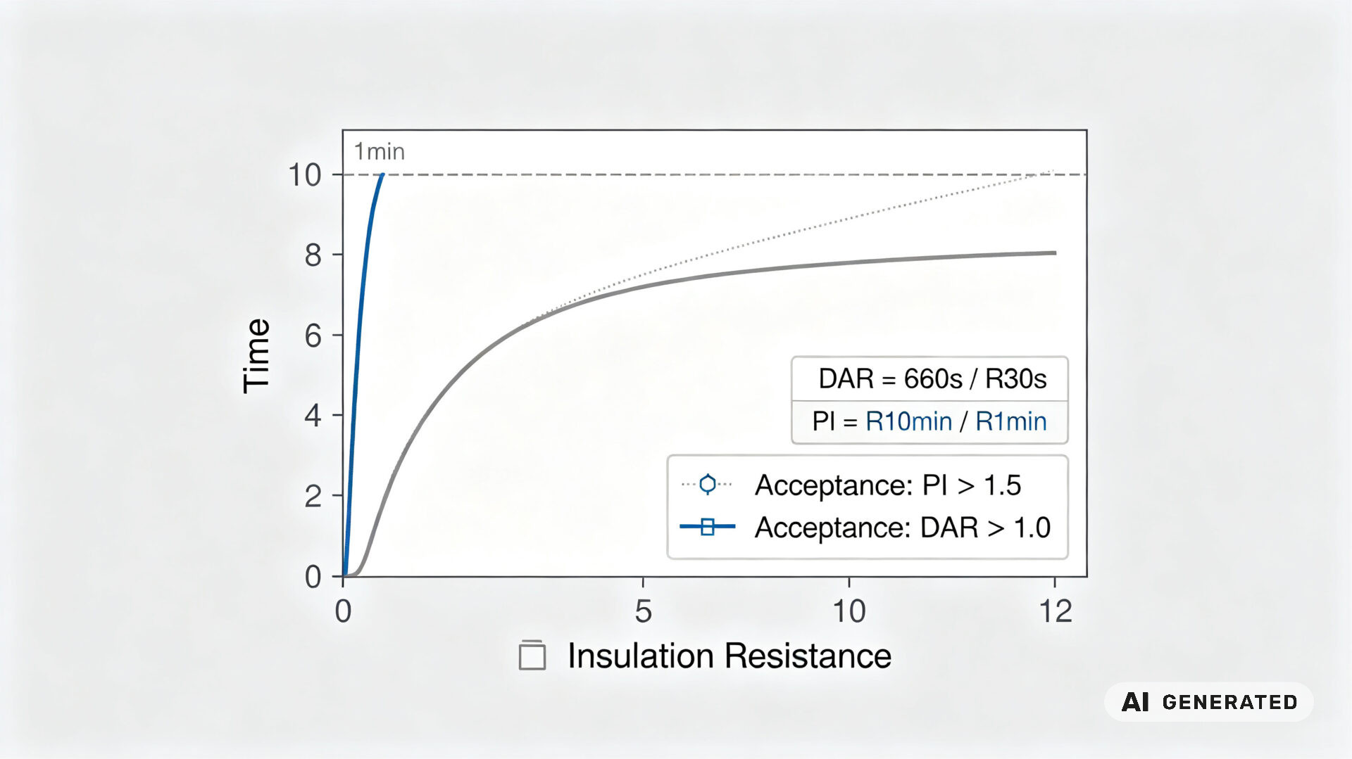
The DAR test improves on the spot test by measuring the insulation resistance at two points in time: 30 seconds and 60 seconds after the test voltage is applied. The ratio of these two readings (R60s / R30s) is the Dielectric Absorption Ratio. In a clean, dry insulation system, the resistance increases over time as the dielectric absorption current decays, producing a ratio greater than approximately 1.25. A DAR value below 1.0 typically indicates moisture or contamination in the insulation. The DAR test is particularly useful for smaller transformers and cables, and is a quick indicator of insulation health.
2.3 Polarization Index (PI)
The Polarization Index test is the most comprehensive of the three methods. The test voltage applied for 10 minutes, and the insulation resistance is recorded at 1 minute and 10 minutes. The ratio (R10min / R1min) is the Polarization Index. For large, high‑voltage equipment, such as power transformers and switchgear, the PI value is a reliable indicator of insulation dryness and overall condition. A PI value above 2.0 is generally considered good. The value between 1.5 and 2.0 suggests marginal insulation. And a value below 1.0 indicates dangerously degraded insulation requiring immediate investigation. TPS performs PI testing in accordance with IEEE 43 guidelines. Which using calibrated Megger instruments and controlled test conditions to ensure accurate, repeatable results. For further insight into our testing methodologies, see the how to test electromagnetic compatibility guide. Which reflects a similar rigor applied to all our electrical testing services.
3. Relevant standards: IEEE 43, IEC 60076, and IEC 60502
Insulation resistance testing governed by several primary international standards. IEEE 43‑2013, the “IEEE Recommended Practice for Testing Insulation Resistance of Electric Machinery,” provides detailed procedures for measuring the insulation resistance of windings, applicable to motors, generators, and transformers. It defines minimum acceptable insulation resistance values based on the rated voltage and temperature. And specifies the test voltages to be used for different equipment classes.
For distribution and power transformers, the IEC 60076 series, specifically IEC 60076‑1 (General), recognizes insulation resistance measurement as a key diagnostic test. For power cables with extruded insulation, IEC 60502 provides guidance on testing procedures and minimum insulation resistance levels for cables rated from 1 kV to 30 kV. TPS conducts all insulation resistance tests in accordance with these standards. And test reports include a statement of compliance, the environmental conditions at the time of testing. Also temperature‑corrected resistance values where applicable.
4. TPS approach: integrating IR testing with comprehensive electrical safety evaluation
TPS Elektronik’s industrial electrical testing service offered through its accredited EMC and electrical safety laboratory. This integration provides a significant advantage: a single partner can evaluate both the insulation condition of critical assets and their electromagnetic compatibility and safety compliance. For maintenance and procurement teams, this reduces the number of test providers and streamlines documentation.
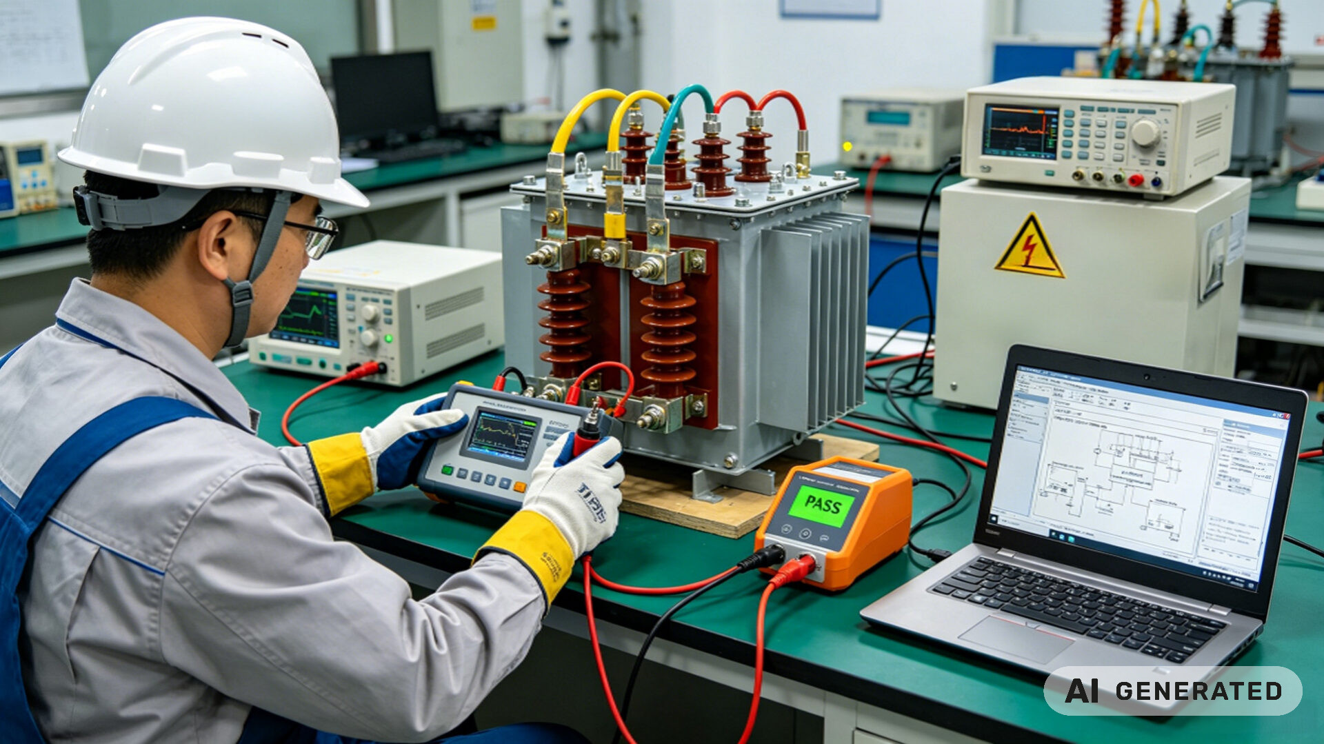
The TPS laboratory is equipped with calibrated Megger instruments capable of delivering test voltages up to 5 kV, as well as environmental chambers for temperature‑controlled testing of cable samples. Every test report includes the raw measurement data, calculated DAR and PI values, a comparison to the relevant standard’s acceptance criteria, and a clear diagnostic recommendation. This documentation supports the customer’s internal maintenance planning and can be used as evidence for insurance underwriting or regulatory compliance. For more on how TPS supports its customers with detailed case studies, see our case study on combined EMC and electrical safety testing.
5. Application scenarios: cables, switchgear, and distribution transformers
- Industrial power cables (XLPE, PILC, EPR): Detects water treeing, insulation degradation, and sheath damage before they cause a short circuit. Both new installation commissioning tests and periodic maintenance tests are performed.
- Medium‑voltage switchgear: Evaluates the integrity of busbar insulation and circuit breaker interrupters, detecting surface contamination and moisture ingress that can lead to arc flash incidents.
- Distribution transformers (up to 10 MVA): Assesses the condition of the winding insulation, detecting moisture ingress and cellulose degradation. This is essential for aging transformer fleet management and determining if an oil reclamation or a complete rewind is necessary.
6. RFQ checklist for insulation resistance testing
- Asset nameplate data: Rated voltage, power rating, insulation class, year of manufacture.
- Test voltage required: Typically 500 V, 1000 V, 2500 V, or 5000 V DC, based on the asset’s rated voltage.
- Test methods: Spot test, DAR, PI, or a combination; specify which phases or windings to test.
- Temperature correction: Provide the temperature of the asset at the time of testing for correction to a reference temperature.
- Previous test data: If available, supply historical IR test results for trending analysis.
- Applicable standards: IEEE 43, IEC 60076, IEC 60502, or customer‑specific requirements.
- Documentation: Required report format, certificate of calibration, and compliance statement.
7. FAQ
What is the recommended test voltage for a 11 kV power cable?
IEEE 43 recommends a test voltage of approximately 1.5 times the rated line‑to‑line voltage, so a 5000 V DC test commonly used for 11 kV cables.
How often should transformer insulation resistance be tested?
A baseline test at installation, followed by periodic testing at intervals of 1 to 3 years, depending on the criticality of the transformer and the operating environment.
What is a good Polarization Index value for a dry‑type transformer?
A PI value above 2.0 generally indicates good insulation condition. Values between 1.5 and 2.0 suggest marginal insulation, and values below 1.0 indicate seriously degraded insulation.
Can TPS perform on‑site testing for large switchgear?
Yes. While TPS primarily performs testing in its laboratory for the most controlled conditions, on‑site testing can arranged for large, difficult‑to‑transport assets.
Where can I learn more about TPS’s broader testing capabilities?
Visit the TPS EMC laboratory service page, or read our resources on EMC testing news and EMC testing case studies.