For system integrators, field maintenance engineers, and electrical technicians supporting multi-axis CNC machines, vibration issues and sensor feedback anomalies are not just quality problems—they are production-stopping events that can cost thousands per hour of downtime. Diagnosing these issues requires an oscilloscope that can capture high-frequency signals across multiple channels simultaneously, analyze accelerometer data in real time, and decode encoder feedback—all while being portable enough to carry to the machine on the factory floor.
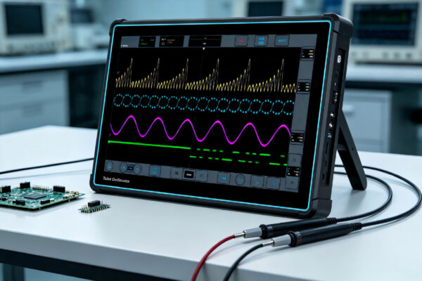
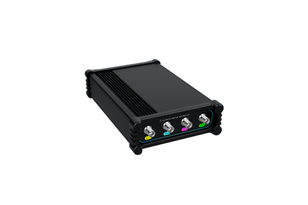
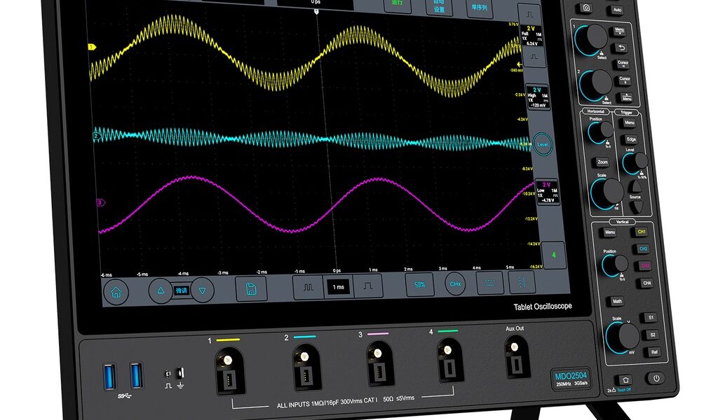
The Micsig MDO5004, available through TPS Elektronik, is a high-performance 4-channel tablet oscilloscope delivering 500MHz bandwidth, 3GSa/s real-time sampling rate, and 360Mpts memory depth. With a 230,000 wfms/s waveform capture rate, <90µVrms noise floor, and a 14-inch anti-glare touch screen, this portable oscilloscope is engineered for field maintenance of CNC machines, servo drives, and industrial automation systems.
1. The CNC Diagnostic Challenge: Vibration and Sensor Feedback
Multi-axis CNC machines are among the most complex electro-mechanical systems in industrial manufacturing. They combine precision mechanical components—spindles, linear guides, ball screws—with sophisticated servo drives, encoders, and PLC-controlled automation. When something goes wrong, the symptoms are often ambiguous: surface finish degrades, positioning errors appear, or the machine produces audible chatter.
Root-cause analysis requires capturing multiple signal types simultaneously:
- Vibration signals from accelerometers mounted on spindles, bearings, and machine structures
- Encoder feedback from servo motors (A/B/Z quadrature signals, SSI, or BiSS protocols)
- Servo drive current and velocity commands from the CNC controller
- PLC I/O signals from sensors, limit switches, and actuators
- Serial bus communications (CAN, CAN FD, RS-232/422/485) between controllers and drives
A multi-channel oscilloscope is essential because these signals must be viewed in time correlation. A vibration spike that coincides with an encoder glitch tells a different story than a vibration spike that occurs independently. The ability to capture four channels simultaneously—with deep memory to record long-duration events and high bandwidth to resolve high-frequency vibrations—is what separates effective diagnostics from guesswork.
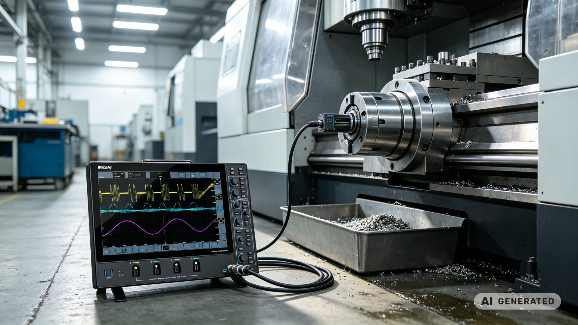
2. Product Overview: MDO5004 4-Channel Tablet Oscilloscope
The Micsig MDO5004 is a 5th-generation digital storage oscilloscope that redefines what a field-portable oscilloscope can deliver. With 500MHz bandwidth, four analog channels, 3GSa/s real-time sampling rate, and 360Mpts memory depth, it provides the performance typically associated with benchtop oscilloscopes in a form factor that fits in a service bag.
Key features for CNC and industrial maintenance:
- 500MHz bandwidth: Captures high-frequency vibration components and fast edge rates from encoder signals
- 4 analog channels: Simultaneously monitor accelerometer, encoder, servo command, and PLC signals
- 360Mpts memory depth: Records long-duration vibration events and intermittent faults without losing resolution
- 230,000 wfms/s waveform capture rate: Captures rare, intermittent glitches that other oscilloscopes miss
- <90µVrms noise floor: Measures low-level accelerometer signals without being swamped by oscilloscope noise
- 14-inch anti-glare touch screen: 1920×1200 resolution for clear waveform visualization in bright factory lighting
- Segmented storage: Captures up to 10,000 events for intermittent signal analysis
- Advanced math and FFT: Frequency-domain analysis for vibration spectrum identification
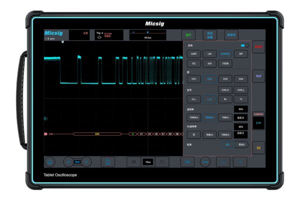
- Comprehensive serial bus decoding: CAN FD, LIN, SPI, I²C, ARINC-429, and MIL-STD-1553B
- Ultra-thin design: 35.8mm thick, supports wall or arm mounting to save bench space
- Built-in battery: 13,500mAh Li-ion for field operation without AC power
For CNC machine vibration testing and sensor feedback diagnostics, the MDO5004 combines the channel count, bandwidth, and memory depth needed to capture the full picture of machine behavior—from spindle vibration harmonics to servo encoder timing errors.
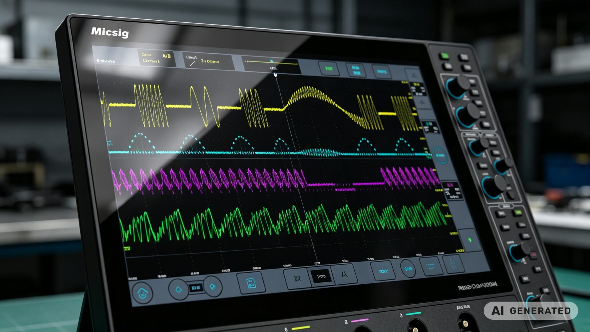
3. Vibration Analysis with Accelerometers and FFT
Machine vibration is the leading indicator of mechanical problems in CNC machining centers. Unbalance in the spindle, worn bearings, misaligned couplings, and loose structural components all produce characteristic vibration signatures that can be detected with accelerometers and analyzed with an oscilloscope.
For accelerometer vibration analysis with the MDO5004, the four channels enable:
- Triaxial accelerometer monitoring: Channels 1–3 capture X, Y, and Z vibration components simultaneously
- Reference signal capture: Channel 4 captures a tachometer or spindle encoder signal for order analysis
- Time-domain waveform analysis: Identify shock events, impacts, and transient vibrations
- Frequency-domain FFT analysis: Convert time-domain vibration data to the frequency domain to identify fundamental frequencies, harmonics, and sidebands that point to specific fault types
Common vibration faults and their FFT signatures:
- Unbalance: Peak at 1× rotational speed with harmonics
- Misalignment: Peaks at 1× and 2× rotational speed with sidebands
- Bearing wear: Broadband noise at high frequencies with specific bearing defect frequencies
- Looseness: Multiple harmonics of rotational speed with high amplitude
- Chatter: High-frequency peaks at structural resonance frequencies
The MDO5004’s advanced math and FFT functions enable real-time spectrum analysis, making it a powerful vibration analysis handheld scope for predictive maintenance programs. By establishing baseline vibration signatures during normal operation, maintenance teams can detect degradation before it leads to catastrophic failure.
For machine condition monitoring applications, the MDO5004’s segmented storage captures intermittent vibration events that might otherwise be missed—such as vibration spikes during specific tool paths or at particular spindle speeds.
4. Encoder Signal Debugging for Servo Drives
Servo drives in CNC machines rely on encoder feedback to maintain precise position and velocity control. Encoder signal integrity issues—noise, timing errors, missing pulses—can cause following errors, position drift, and axis vibration that manifests as poor surface finish or dimensional inaccuracies.
For encoder signal debugging with the MDO5004:
- Quadrature encoder signals (A/B/Z): Capture A and B channels for velocity and direction, Z channel for reference position
- Differential signaling: Use two channels for A+/A- or B+/B- to verify differential signal integrity
- Serial encoder protocols: Decode SSI, BiSS, or EnDat protocols with the oscilloscope’s serial decoding capabilities
- Timing measurements: Measure rise times, fall times, pulse widths, and phase relationships between A and B channels
- Noise analysis: Identify induced noise, ground loops, or cable shielding issues that corrupt encoder signals
Typical encoder fault patterns visible on an oscilloscope:
- Slow rise/fall times: Indicates cable capacitance or driver issues—can cause missed counts
- Ring: Indicates impedance mismatch or poor termination—causes false triggering
- Missing pulses: Indicates intermittent connection or encoder failure—causes position errors
- Common-mode noise: Indicates grounding issues—causes erratic behavior
- Timing skew: A/B phase relationship outside specification—causes velocity ripple
The MDO5004’s 4-channel capability is essential for encoder debugging because it allows simultaneous capture of A, B, Z, and a reference signal (such as the servo drive’s current command) to correlate encoder behavior with drive commands. For servo tuning portable scope applications, the oscilloscope’s high bandwidth and deep memory capture the dynamics of servo response during acceleration, deceleration, and constant velocity segments.
5. Sensor Feedback and PLC I/O Debugging
CNC machines are controlled by PLCs that monitor hundreds of sensors—limit switches, proximity sensors, pressure transducers, temperature sensors, and more. Sensor feedback anomalies can cause machine faults, unexpected stops, or incorrect tool positioning.
For sensor feedback diagnostics with the MDO5004:
- Analog sensor signals: Capture 0–10V or 4–20mA sensor outputs to verify proper operation
- Digital I/O signals: Capture PLC discrete inputs and outputs with timing analysis
- PWM signals: Measure duty cycle and frequency of pulse-width modulated control signals
- Serial communications: Decode RS-232/422/485, CAN, or CAN FD between PLCs, drives, and HMIs
- Power supply validation: Verify DC power rails for noise, ripple, and dropouts that could affect sensor accuracy
For PLC debugging applications, the MDO5004’s serial bus decoding capability is particularly valuable. Many CNC machines use CAN or CAN FD for communication between the CNC controller, servo drives, and I/O modules. The oscilloscope can decode these messages in real time, revealing communication errors, timing violations, or protocol faults that cause intermittent machine behavior.
The segmented storage function captures up to 10,000 events, making it ideal for diagnosing intermittent faults that occur only occasionally—such as a sensor that fails to trigger at a specific point in a tool path or a communication error that appears only under certain operating conditions.

For tablet oscilloscope for PLC debugging applications, the MDO5004’s intuitive touch interface and portability make it the ideal tool for troubleshooting on the factory floor, where benchtop oscilloscopes are impractical.
6. Field Portability: Battery Power and Ultra-Thin Design
CNC machine diagnostics rarely happen on a clean lab bench. They happen on the factory floor, in machine shops, and in production environments where space is tight and AC power outlets may be distant. The MDO5004’s field-portable design addresses these realities:
- 13,500mAh Li-ion battery: Provides hours of continuous operation without AC power
- 35.8mm ultra-thin body: Slides into a service bag alongside other tools
- 14-inch touch screen: Large enough for clear waveform viewing, yet the overall form factor remains compact at just 400×280×35.8mm
- Wall/arm mounting support: Frees up bench space or can be mounted near the machine for extended monitoring
- Power-off lock: Prevents accidental power-on during transport, preserving battery charge
For field maintenance tablet scope applications, the MDO5004 eliminates the trade-off between portability and performance. It delivers the channel count, bandwidth, and memory depth of a benchtop oscilloscope in a package that can be carried to the machine, set up in minutes, and operated with a familiar touch-screen interface.
The Wi-Fi and USB connectivity enable remote monitoring and data transfer, allowing engineers to capture waveforms on the factory floor and analyze them at their desk—or share them with remote support teams. For predictive maintenance tablet scope programs, the MDO5004 supports routine vibration monitoring and trend analysis without requiring specialized vibration analysis equipment.
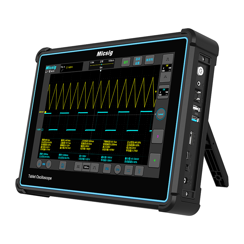
7. Technical Specifications at a Glance
| Parameter | Specification |
|---|---|
| Model | Micsig MDO5004 |
| Bandwidth | 500 MHz |
| Analog Channels | 4 |
| Real-time Sampling Rate | 3 GSa/s |
| Memory Depth | 360 Mpts |
| Waveform Capture Rate | 230,000 wfms/s |
| Noise Floor | <90 µVrms |
| Display | 14-inch anti-glare touch, 1920×1200 |
| Battery | 13,500mAh Li-ion |
| Segmented Storage | Up to 10,000 events |
| Serial Bus Decoding | CAN FD, LIN, SPI, I²C, RS-232/422/485/UART, ARINC-429, MIL-STD-1553B |
| Connectivity | USB 3.0 Host, USB Type-C, LAN, HDMI, Trigger Out |
| Dimensions (W×H×D) | 400×280×35.8 mm |
| Weight | 4.3 kg |
| Rise Time | ≤0.7 ns |
| Remote Control | PC, mobile app, SCPI commands |
| Internal Storage | 32 GB |