

For system integrators, panel builders, and engineering-driven procurement teams, selecting a power supply for automated test sequences is not only about voltage and current ratings.
It also involves the remote command interface, the stability of the setpoint at the device under test, the readback accuracy that the test sequence depends on, and whether the instrument can be integrated into a LabView, Python, or TestStand controller without bespoke driver development.
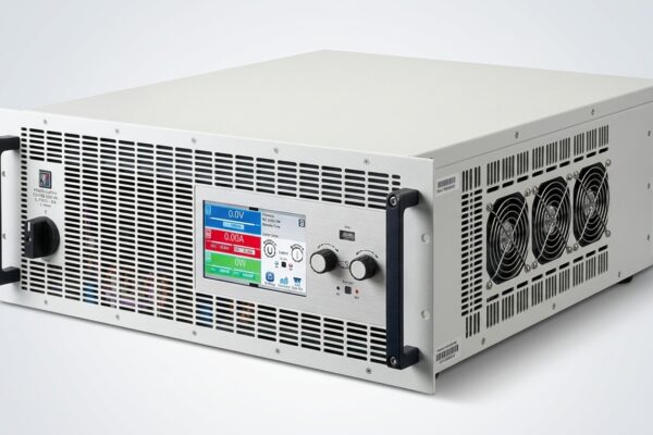
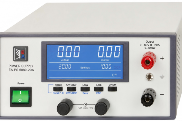
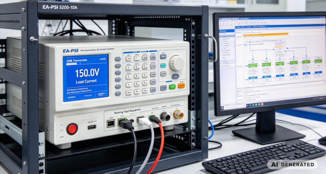
The EA-PSI 5200-10A is a microprocessor-controlled programmable DC power supply with 90–264VAC input, 0–200VDC / 0–10A / 640W auto-ranging output, <30mV RMS ripple, and SCPI command language support alongside LabView VIs and Windows control software. This article explains how to use it as the programmable 150V-class source in an automated test sequence, and what to verify before integrating it into an ATE rack.
1. Why SCPI matters for automated test sequences
An automated test sequence is a sequence of instrument commands, not a sequence of manual dial adjustments. The controller must set a voltage, enable the output, wait for the DUT to settle, measure voltage and current, and repeat—hundreds or thousands of times, without operator intervention.
1.1 SCPI on top of IEEE 488.2
SCPI (Standard Commands for Programmable Instruments) builds on the programming syntax of IEEE 488.2 to provide a common command set that can used over any hardware link—USB, Ethernet, GPIB, or serial. The value for an ATE integrator is portability: the same test script structure can reused across instruments that implement SCPI, and the IEEE 488.2 common commands (reset, self-test, status operations) are defined consistently.
The EA-PSI 5000 A series supports SCPI command language and supplied with LabView VIs and Windows control software. The programming details for the USB interface and the protocol are documented in the manufacturer’s “Programming Guide ModBus & SCPI”.
1.2 The command set a test sequence actually needs
A typical 150V ATE sequence uses a small subset of the full command tree. The essential commands are:
- VOLTage <value> — sets the output voltage setpoint
- CURRent <value> — sets the current limit
- OUTPut ON | OFF — enables or disables the output
- MEASure:VOLTage? — reads back the actual output voltage
- MEASure:CURRent? — reads back the actual output current
- SYSTem:ERRor? — checks for command errors before proceeding
For a sequence that steps through multiple voltage points, the script sets VOLTage, waits for the settling time, then issues MEASure queries. The settling time must verified on the actual load, because the supply’s load regulation time specification (<1.5ms for this model) is measured at the terminals, while the DUT may add its own input capacitance and slow the response.
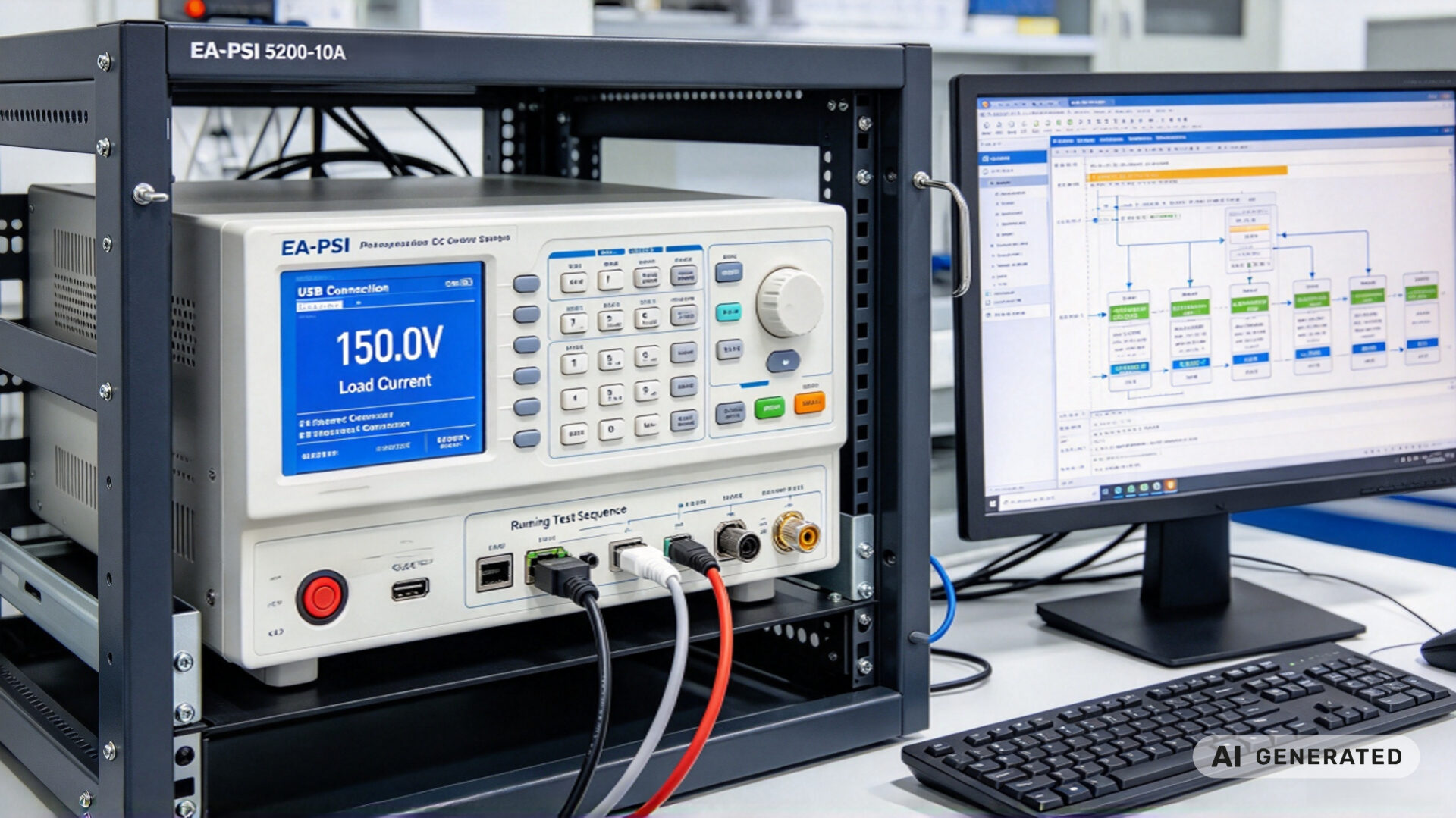
2. How the EA-PSI 5200-10A fits a 150V ATE role
The EA-PSI 5200-10A is a 640W auto-ranging supply with a 0–200VDC output. In a 150V ATE application, it not operated at its maximum voltage; it is operated at a comfortable point within the auto-ranging envelope, which leaves headroom for load transients and cable drop.
2.1 Output range, ripple, and readback
At a 150V setpoint, the supply’s <30mV RMS ripple is a small fraction of the output, and the <0.2% voltage accuracy supports a readback that the test sequence can trust without an external DMM for every point. The auto-ranging stage allows higher current at lower voltage or higher voltage at lower current within the 640W envelope, so the same instrument can cover 150V logic tests and lower-voltage, higher-current tests in the same rack.
2.2 USB, Ethernet, and the control software stack
The supply provides USB and Ethernet interfaces, and supplied with LabView VIs and Windows control software. For an ATE integrator, the practical path is usually one of three options:
- LabView: use the supplied VIs or the SCPI driver, and wrap the sequence in a LabView state machine.
- Python / PyVISA: send SCPI strings over the VISA resource, which is portable across USB and Ethernet.
- TestStand or a custom C# controller: use the SCPI command set directly, or wrap the LabView VIs as a step.
The 9 preset memory groups and the recall function are useful during sequence development: a known state can be recalled before each test step, which reduces the risk of a previous step leaving the output in an unexpected condition.
2.3 Remote sensing and setpoint accuracy at the DUT
At 150V and 10A, the voltage drop in the test leads is not negligible. If the leads have 100mΩ total resistance, a 10A load drops 1V—far larger than the supply’s accuracy specification. Remote sensing at the DUT terminals closes the regulation loop at the load, so the setpoint the test sequence commands is the voltage the DUT actually receives. Without remote sensing, the sequence is programming a voltage at the supply output, not at the device.
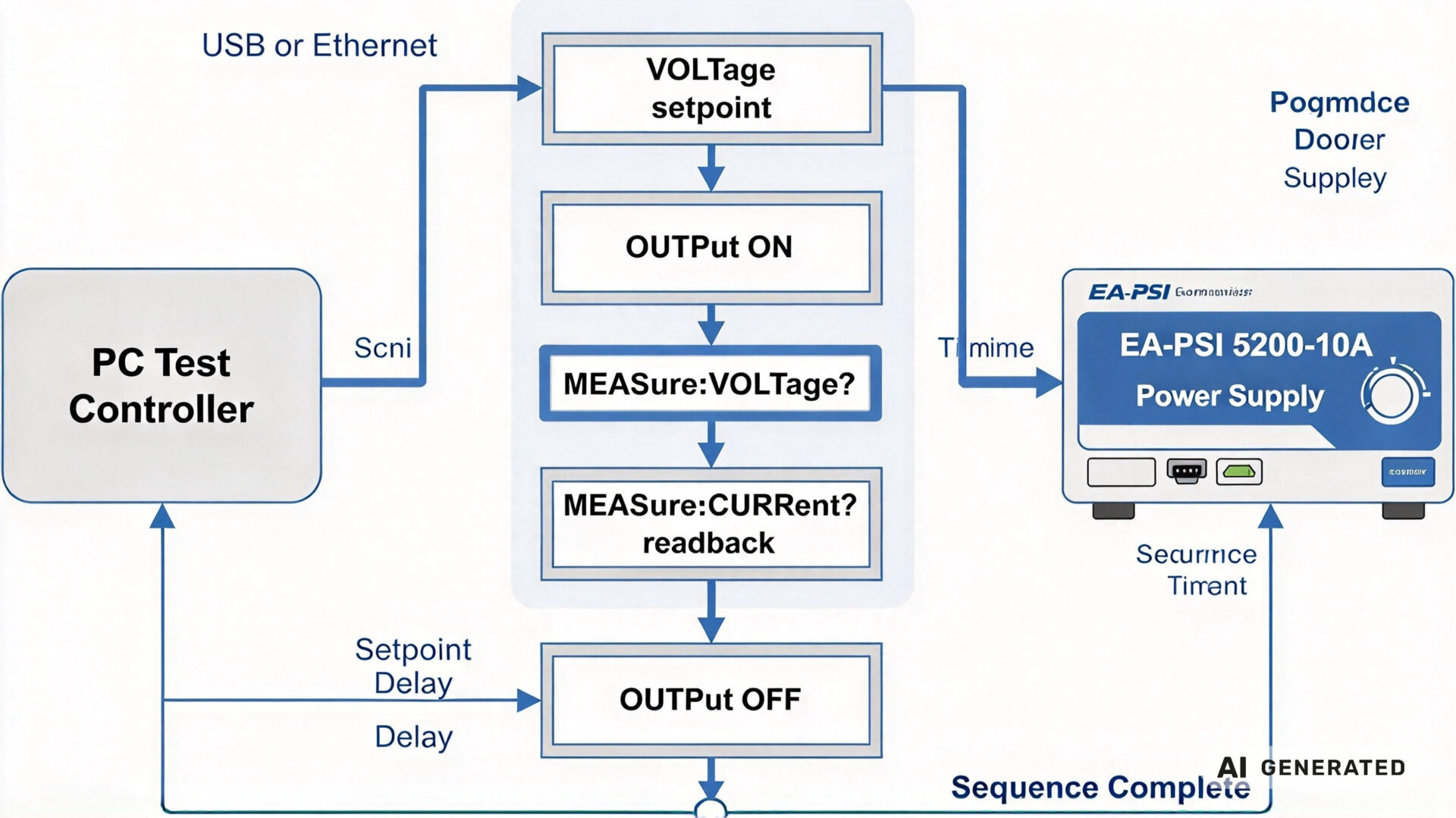
3. Sequencing and timing in an automated test
Power supply sequencing is not unique to multi-rail systems. In a single-rail ATE sequence, the timing of output enable, settling, measurement, and output disable determines whether the test result is valid or noisy.
3.1 Power-up and power-down sequencing
For a single supply powering a DUT with multiple internal rails, the order in which those rails come up may be defined by the DUT datasheet. The supply can implement this by setting VOLTage to the first rail value, enabling OUTPut, waiting, then stepping to the next value—provided the DUT’s internal regulators tolerate the sequence. For a DUT that requires a controlled ramp, the supply’s programmable setpoint steps can be timed by the controller; the Keysight application notes on sequencing multiple modules describe the same principles of delay-based sequencing and fault-triggered shutdown.
3.2 Measurement synchronization and settling time
The most common ATE sequencing error is measuring too early. After a VOLTage step, the supply’s output recovers within its load regulation time, but the DUT’s input capacitance and the cable inductance add an additional settling tail. The test sequence should wait for a settling time that has measured on the actual DUT, not assumed from the supply datasheet. The MEASure:VOLTage? and MEASure:CURRent? queries then return the actual values, and the sequence can compare them against limits before proceeding.
For sequences that require faster throughput, the controller can overlap commands across multiple instruments—for example, setting the next voltage point while the DMM measures the current point—which is the standard technique for reducing ATE test time with multiple supplies.
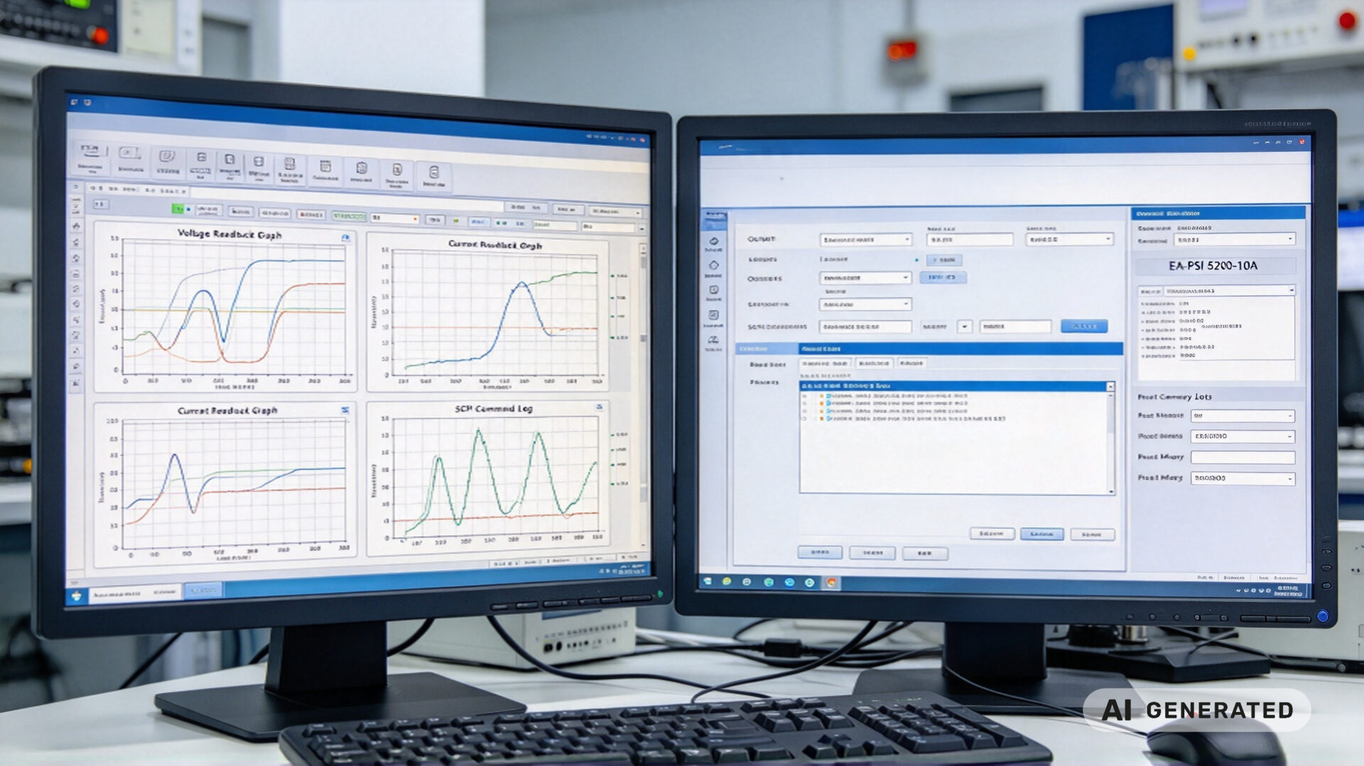
4. Integration checklist for an ATE rack
Before the supply mounted in the rack and the first SCPI script is run, the following items should be verified. This list is the difference between a sequence that runs unattended and one that requires an engineer to babysit every step.
- Interface selection: USB for a single rack PC, Ethernet for a networked test cell. Confirm the VISA resource string and the instrument’s IP configuration.
- Remote/Local state: The supply does not automatically enter remote mode on receiving a command; remote control must be explicitly activated, and a Local state can lock out remote commands. The sequence should include an explicit remote-enable step and a recovery path.
- Protection settings: Set OVP just above the maximum test voltage and OCP just above the maximum test current. The supply’s OVP, OCP, OPP, and overtemperature protections are adjustable and should be configured before the sequence starts.
- Remote sense: Connect sense leads at the DUT terminals, not at the supply output, and verify the readback matches an external DMM at the DUT.
- Settling time: Measure the actual settling time at the DUT for a representative voltage step, and use that value in the sequence.
- Error handling: After each command block, query SYSTem:ERRor? and log the result. A silent command error is the most common cause of a “mysterious” test failure.
- Documentation: Keep the SCPI command list, the interface configuration, and the timing diagram in the ATE documentation package, so the sequence can be maintained by someone other than its author.
The element testing laboratories resource and the quality assurance customer case describe how TPS supports test-lab integration and validation.
5. Product specifications
| Parameter | EA-PSI 5200-10A | Typical manual bench supply |
|---|---|---|
| Input | 90–264VAC, 45–65Hz | 115/230VAC selectable |
| Output | 0–200VDC / 0–10A / 640W, auto-ranging | 0–30V / 0–5A, fixed range |
| Ripple | <30mV RMS | Often unspecified |
| Voltage accuracy | <0.2% | 0.5–1% |
| Remote interface | USB, Ethernet, SCPI, LabView VIs | USB optional |
| Preset memory | 9 groups | 2–4 |
| Remote sense | Yes | Usually no |
| Typical use | Automated test, ATE, lab automation | Manual bench work |
The comparison shows where the specification matters for ATE: the remote interface, the readback accuracy, and the remote sense are the features that make unattended sequencing possible.
6. RFQ checklist
To streamline quotation and integration review for a 150V power supply used in automated test sequences, provide the following:
- Voltage and current range: Maximum test voltage, maximum load current, and whether the 150V point is continuous or stepped
- Interface requirement: USB, Ethernet, GPIB, or a combination, and the controller environment (LabView, Python, TestStand, C#)
- SCPI command coverage: Which commands the sequence will use, and whether any instrument-specific commands are required
- Sequencing requirement: Number of voltage steps, settling time, and measurement points per step
- Remote sense: Whether sensing at the DUT is required
- Rack and cooling: Rack height, airflow, and ambient temperature
- Documentation: SCPI programming guide, LabView VI library, and calibration certificate
- Quantity and schedule: Single unit, multi-rack rollout, and delivery milestones
Providing these details reduces clarification cycles. TPS’s engineering team can support interface selection, sequence timing review, and integration planning as part of the RFQ process.