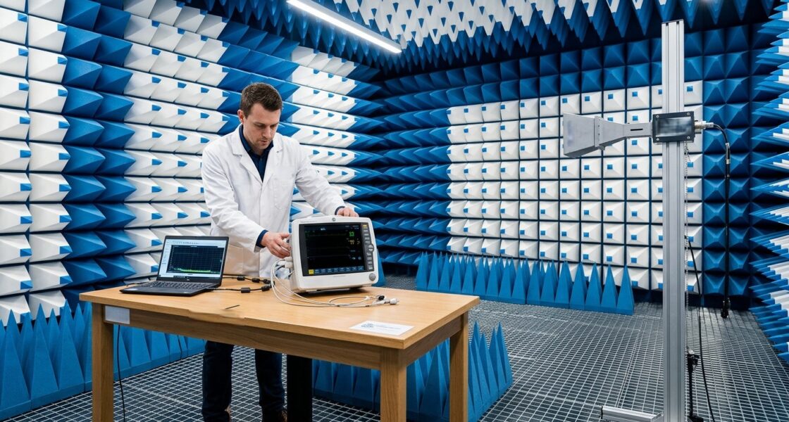
System integrators, panel builders, and electrical engineers designing industrial variable frequency drives (VFDs) face a persistent challenge: meeting the harmonic and emission limits of IEC 61800-3. A single failed EMC test at an accredited laboratory can cost thousands in re-test fees, delay product launch by weeks, and force costly redesigns of filters, shielding, and PCB layout.
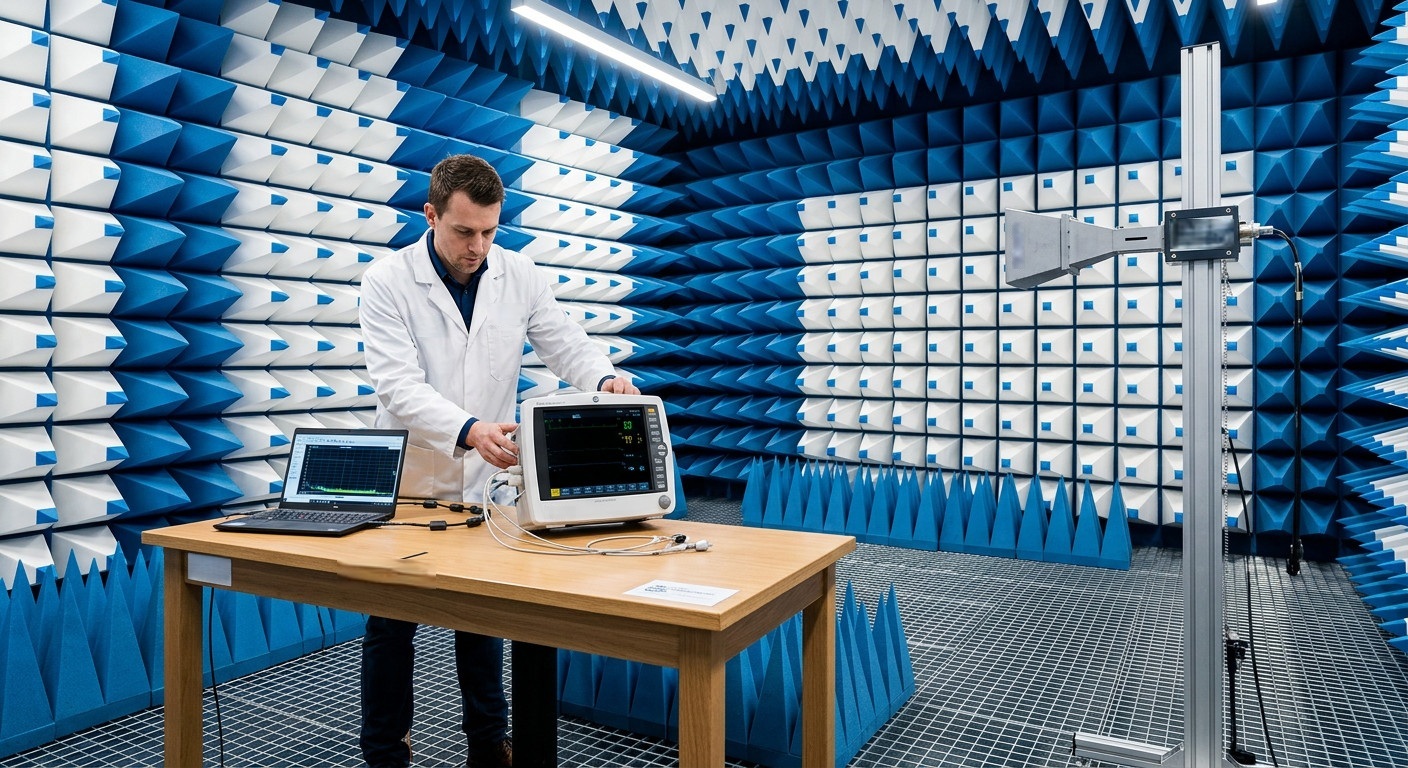
TPS Elektronik’s EMC testing services built to reduce that risk: pre-compliance testing for conducted and radiated emissions, harmonic analysis per IEC 61800-3, immunity testing, and filter design support—so that issues are resolved before formal certification begins.
1. IEC 61800-3 Overview: The EMC Product Standard for Adjustable Speed Drives
IEC 61800-3 is the international EMC product standard for adjustable speed electrical power drive systems (PDS) and machine tools. It specifies electromagnetic compatibility (EMC) requirements for adjustable speed AC or DC motor drives with converter input and/or output voltages up to 35 kV AC RMS. The standard defines minimum requirements for both emission and immunity in the frequency range from 0 Hz to 400 GHz.
For variable frequency drives (VFDs) destined for the European market, compliance with IEC 61800-3 (published as EN 61800-3) is essential for CE marking under the EMC Directive 2014/30/EU. The standard addresses two primary EMC concerns:
- Low-frequency emissions (below 150 kHz): primarily harmonics and voltage distortion caused by the VFD’s rectifier stage
- High-frequency emissions (above 150 kHz): conducted and radiated emissions from the VFD’s switching power stage
The standard also defines immunity requirements to ensure that VFDs operate reliably in the presence of electromagnetic disturbances from other equipment.
IEC 61800-3 was most recently updated in 2022, with key changes including an extension of the frequency range for radiated immunity tests to 6 GHz. Staying current with these evolving requirements is critical for manufacturers and system integrators seeking market access.
2. Understanding the Four Emission Categories: C1, C2, C3, and C4
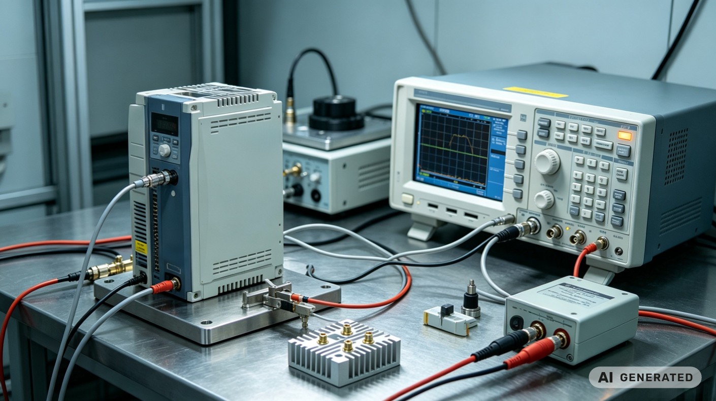
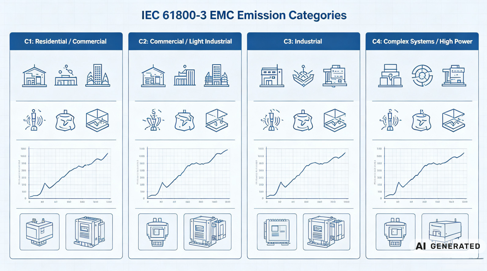
IEC 61800-3 defines four emission categories—C1, C2, C3, and C4—that determine the applicable emission limits and test requirements for a VFD. The category determined by the drive’s intended installation environment and electrical characteristics.
Category C1 applies to PDS equipment with a rated voltage below 1000 V, intended for use in the first environment—residential, commercial, and light industrial locations. This is the most stringent category, with the lowest emission limits, because equipment must not interfere with consumer electronics and sensitive equipment. Category C1 VFDs must comply with Class B limits per EN 55011.
Category C2 applies to PDS equipment with rated voltage below 1000 V, intended for use in the first environment but not pluggable or movable—typically permanently installed equipment in commercial or light industrial settings. Emission limits are less stringent than C1 but still require careful filter design.
Category C3 applies to PDS equipment with rated voltage below 1000 V, intended for use in the second environment—industrial locations where equipment not connected to a low-voltage public network. This is the most common category for industrial VFDs, with limits that exceed those of generic emission standard IEC 61000-6-4.
Category C4 applies to PDS equipment with rated voltage ≥1000 V or rated current ≥400 A, typically used in complex industrial systems. These drives require site-specific EMC planning and often demand custom filtering solutions.
Correctly identifying the applicable category is the first step toward compliance. A VFD intended for a residential environment (Category C1) will require significantly more filtering than one destined for a factory floor (Category C3).
3. Harmonic Emissions: The Low-Frequency Challenge
Harmonic emissions are one of the most common compliance hurdles for VFD manufacturers and system integrators. The non-linear input rectifier of a VFD draws current in pulses rather than a smooth sinusoidal waveform, injecting harmonic currents into the AC mains. These harmonics can cause voltage distortion, interfere with other equipment, and exceed the limits defined in IEC 61800-3.
IEC 61800-3 addresses harmonic emissions through requirements that reference the IEC 61000-3 series of standards:
- IEC 61000-3-2 applies to equipment with input current ≤16 A per phase
- IEC 61000-3-12 applies to equipment with input current >16 A and ≤75 A per phase
For equipment with input current exceeding 75 A per phase, harmonic limits typically addressed through site-specific agreements with the utility or through the application of IEC 61800-3’s harmonic emission requirements.
Harmonic currents characterized by their frequency—multiples of the fundamental 50 Hz or 60 Hz supply frequency. The third harmonic (150 Hz or 180 Hz), fifth harmonic (250 Hz or 300 Hz), and seventh harmonic (350 Hz or 420 Hz) are typically the most significant. Total harmonic distortion (THD) must be managed to stay below applicable limits.
Common mitigation strategies for harmonic emissions include:
- Active front-end (AFE) rectifiers that actively shape the input current waveform
- Passive harmonic filters tuned to attenuate specific harmonic frequencies
- Multi-pulse rectifiers (12-pulse, 18-pulse, 24-pulse) that cancel lower-order harmonics
- DC link chokes that reduce the ripple and distortion of the input current
TPS Elektronik’s EMC testing services include harmonic analysis to identify which harmonics are exceeding limits and to quantify the effectiveness of mitigation measures.
4. Conducted Emissions: 150 kHz to 30 MHz
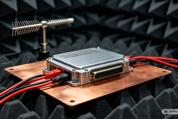
Conducted emissions are disturbances that propagate from the VFD back into the AC mains through the power cables. These emissions occur in the frequency range from 150 kHz to 30 MHz and are measured using a line impedance stabilization network (LISN) and a spectrum analyzer or EMI receiver.
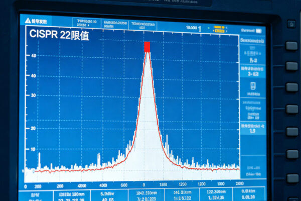
The conducted emission limits in IEC 61800-3 vary by category. For Category C1 (residential environments), limits are comparable to EN 55011 Class B, with quasi-peak limits of approximately 66–56 dBµV and average limits of 56–46 dBµV over the 150 kHz to 30 MHz range. Category C3 (industrial environments) allows higher emission levels.
Key factors influencing conducted emissions in VFDs include:
- Switching frequency—higher switching frequencies can shift noise to higher frequencies where filtering is easier, but also increase high-frequency emissions
- Diode recovery characteristics—fast recovery diodes generate less noise but may increase cost
- PCB layout and grounding—poor layout can create unintended antennas that radiate noise back into the input lines
- Cable routing and shielding—unshielded or improperly routed cables can couple noise from the output side back to the input
Conducted emissions are measured on both the power input lines and control/signal lines. The test setup must follow the specific requirements defined in IEC 61800-3, including proper cable routing, grounding, and LISN placement.
5. Radiated Emissions: 30 MHz to 6 GHz
Radiated emissions are electromagnetic fields that propagate through space from the VFD, its cables, and its enclosure. These emissions occur in the frequency range from 30 MHz to 6 GHz (the 2022 edition extended the upper limit from 1 GHz to 6 GHz for immunity tests).
Radiated emissions measured using antennas positioned at specified distances—typically 3 meters for small equipment or 10 meters for larger installations. The limits vary by category, with Category C1 being the most stringent.
Key sources of radiated emissions in VFDs include:
- Fast switching edges—the rapid voltage and current changes in the IGBTs or MOSFETs create high-frequency components that radiate
- Motor cable radiation—the cables between the VFD and the motor can act as efficient antennas, radiating switching noise
- Enclosure seams and openings—unshielded seams, ventilation slots, and connector openings can allow electromagnetic fields to escape
- Control and signal cables—unshielded control cables can radiate noise and couple it into other circuits
Mitigation strategies for radiated emissions include:
- Proper shielding—using shielded motor cables with properly terminated shields
- Output filters—sine-wave filters or dV/dt filters to smooth the output voltage waveform
- Enclosure design—continuous conductive seams, proper gasketing, and screened ventilation openings
- Component placement—keeping high-frequency switching components away from cables and openings
For industrial drive EMC compliance, radiated emissions are often the most difficult to address because they depend on installation details—cable routing, grounding practices, and enclosure design—that may vary from one installation to another. TPS’s EMC laboratory can evaluate both the drive itself and the complete installation to identify and resolve radiated emission issues.
6. Filter Design Support: Solving EMC Issues at the Source
Addressing EMC issues through filtering is often more cost-effective than redesigning PCBs or enclosures. TPS Elektronik provides filter design support as part of its EMC testing services, helping clients identify the right filtering solutions for their VFD applications.
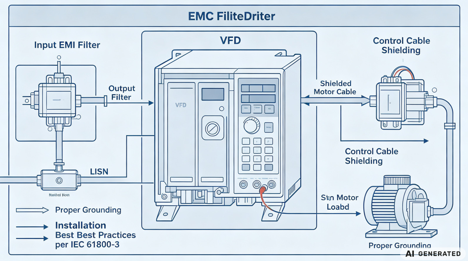
IEC 61800-3 requires that EMC filters be selected and installed according to the standard’s requirements. Common filter types used in VFD applications include:
- Input EMI filters—installed on the AC mains side to reduce conducted emissions back into the grid
- Output filters—installed on the motor side to reduce radiated emissions and protect the motor from switching transients
- Common-mode chokes—attenuate common-mode currents that contribute to both conducted and radiated emissions
Filter selection must account for several factors:
- Required emission category—C1 requires more aggressive filtering than C3
- Switching frequency—filters must be effective at the switching frequency and its harmonics
- Motor cable length—longer cables require more filtering to suppress radiation
- Line and load impedance—filters must be compatible with the specific impedance of the installation
TPS’s filter design support includes:
- Pre-compliance measurement—identifying which frequencies exceed limits and by how much
- Filter specification—recommending appropriate filter types, component values, and manufacturers
- Installation guidance—providing instructions for proper filter placement, grounding, and cable routing
- Verification testing—re-testing after filter installation to confirm compliance
For industrial EMC filter design applications, TPS’s EMC laboratory can evaluate filter effectiveness under real-world conditions, identifying any interactions between the filter and the drive that might degrade performance.
7. The Pre-Compliance Advantage: Catching Issues Early
Formal EMC testing at accredited laboratories is expensive and time-sensitive. A single failure can cost thousands in re-test fees and weeks in schedule delays. Pre-compliance testing is the countermeasure.
At TPS, our pre-compliance testing approach is integrated with our broader EMS and engineering services. We perform conducted and radiated emissions testing, harmonic analysis, and immunity testing on prototypes, pilot units, and even early production samples. The goal is not just to pass tests, but to identify and resolve EMC issues before they reach formal certification.
Our process for IEC 61800-3 compliance includes:
- Design review—assessing schematics, PCB layout, mechanical design, and cable routing for EMC risk factors
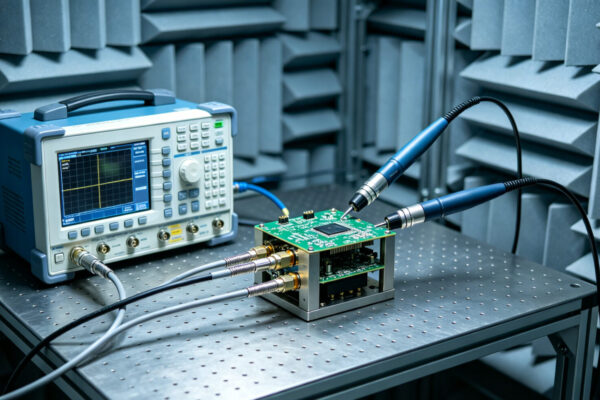
- Pre-compliance measurement—running the same tests as accredited labs would, using calibrated equipment and standard-compliant methods
- Harmonic analysis—identifying harmonic distortion levels and sources
- Iterative improvement—making changes—filtering, layout adjustments, shielding additions—and re-testing to verify effectiveness
- Documentation—providing test reports that can referenced during formal certification
This approach is especially valuable for VFD manufacturers and system integrators where EMC issues can be costly to fix late in the development cycle. By catching issues early, TPS helps clients avoid the cost and delay of redesigning filters, shielding, and PCB layouts after formal testing has already been attempted.
For power electronics EMC testing applications, TPS’s EMC laboratory is equipped to handle the unique challenges of high-power, high-voltage VFDs—including the high currents and fast switching transients that characterize these systems.
Request an IEC 61800-3 pre-compliance test →