For system integrators and panel builders working with high-power semiconductor modules, thermal management is not a secondary concern. It directly determines whether an IGBT inverter or a MOSFET-based motor drive survives its first thermal cycle or fails catastrophically in the field. When junction temperature exceeds the rated maximum — typically 150 °C for silicon IGBTs and 175 °C for SiC MOSFETs. The device experiences accelerated degradation, parameter drift, and eventual destruction.
Selecting a properly designed aluminum heat sink is the most direct engineering intervention available. TPS Elektronik provides a curated range of custom aluminum heat sinks that address the complete thermal path. Which from the semiconductor junction through the case, across the thermal interface. And into ambient air via either natural or forced convection. Understanding how to manage aluminum heat sink thermal resistance and the junction temperature calculation is critical to reliable system design.
The thermal path: from junction to ambient
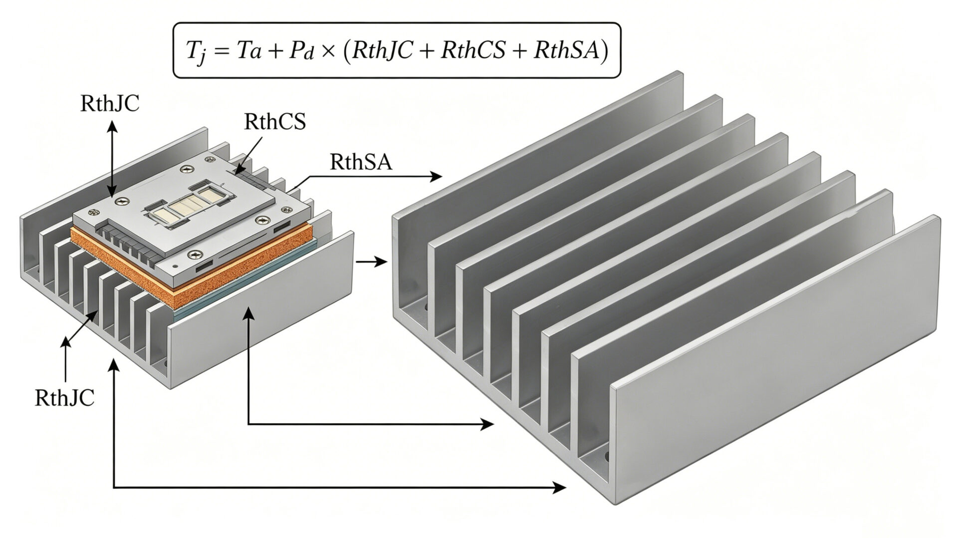
Every power semiconductor operates within a thermal resistance network. Heat generated at the silicon junction must traverse multiple interfaces before reaching ambient air. The total thermal resistance from junction to ambient is expressed as:
RthJA = RthJC + RthCS + RthSA
Here, RthJC is the junction-to-case thermal resistance. A fixed value determined by the semiconductor manufacturer and documented in the device datasheet per IEC 60747-9 for IGBTs. RthCS represents the case-to-sink thermal resistance, which depends almost entirely on the quality of the thermal interface: surface flatness, mounting pressure, and the thermal conductivity of the interface material. RthSA is the sink-to-ambient thermal resistance, which is determined by the heat sink geometry, material, surface treatment, and airflow conditions.
The junction temperature is then calculated as:
Tj = Ta + Pd × RthJA
where Ta is ambient temperature and Pd is the total power dissipation. For an IGBT module dissipating 200 W in a 40 °C environment, a total RthJA of 0.5 K/W results in a junction temperature of 140 °C — dangerously close to the typical 150 °C limit. Reducing RthJA by selecting a lower-resistance heat sink directly lowers Tj and extends device lifetime.
The three thermal resistance components are not equally controllable. RthJC is fixed by the semiconductor package and cannot be changed. RthCS can be minimized through careful surface preparation and appropriate thermal interface material selection — a topic covered later in this article. RthSA is where the system integrator or panel builder has the most influence, because the heat sink geometry, material, and cooling strategy are entirely under the designer‘s control. For a deeper understanding of how aluminum heat sinks perform across different scenarios, refer to TPS’s detailed analysis on aluminum heat sink efficiency across cooling scenarios.
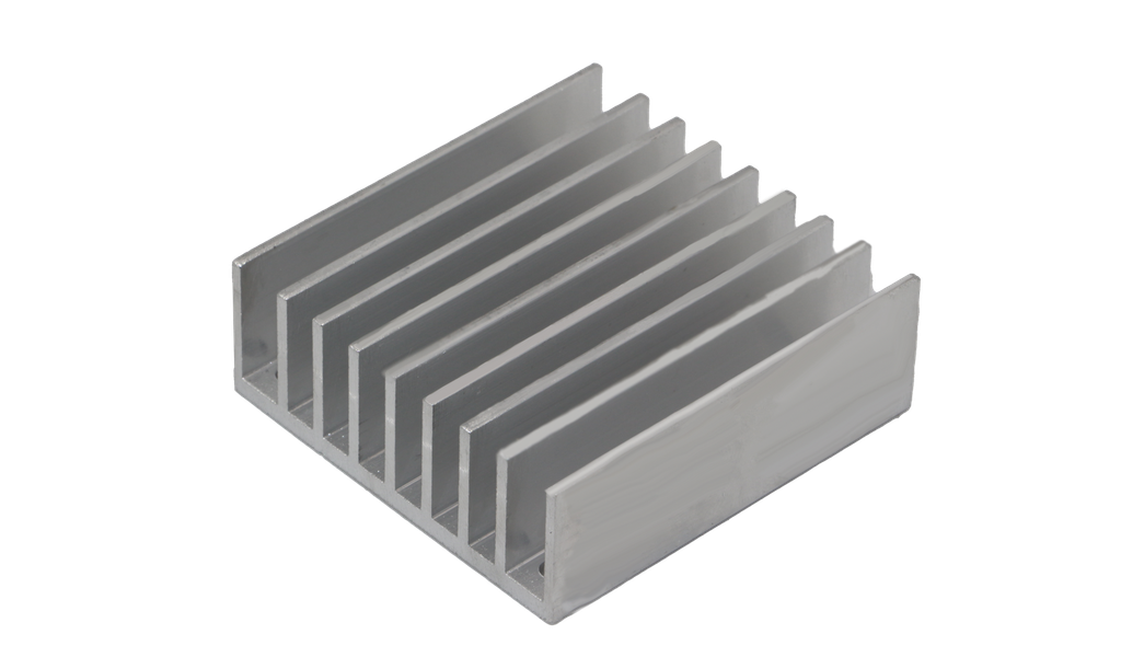
Heat sink design parameters: fin geometry, surface area, and airflow
The performance of an aluminum heat sink is governed primarily by its geometric design. Fins increase the surface area available for convective heat transfer — the dominant cooling mechanism, accounting for 70–90% of total heat dissipation in a well-designed heat sink. Key design parameters include fin height, fin thickness, fin spacing, and base plate thickness. Each parameter involves trade-offs that affect thermal resistance, weight, cost, and manufacturability.
Taller fins increase surface area but also increase the conductive path length from the base to the fin tip. Thinner fins allow more fins per unit width but reduce structural rigidity and can vibrate under forced airflow. Fin spacing is particularly critical: in natural convection, wider spacing (typically 8–15 mm) allows buoyancy-driven airflow to develop without interference between adjacent boundary layers. In forced convection, denser fin arrangements (2–5 mm spacing) become practical because the fan or blower overcomes the flow resistance. Which enabling higher heat transfer rates per unit volume.
The base plate thickness determines how effectively heat spreads laterally from the semiconductor mounting area to fins farther from the heat source. A thicker base plate improves spreading but adds weight and material cost. For IGBT modules with concentrated heat sources, base thicknesses of 8–12 mm are common. For distributed heat sources like multiple MOSFETs, thinner bases may suffice.
TPS‘s standard heat sink product line — including HS1006 (57.9 × 21 × 37 mm) and HS1005 (57.9 × 21 × 60 mm). Which provides off-the-shelf solutions for smaller power devices. For higher-power IGBT and MOSFET applications requiring custom geometries, TPS offers design and manufacturing services that tailor fin geometry, base dimensions, and mounting features to specific thermal requirements.
Natural convection vs. forced convection: decision criteria
The choice between natural and forced convection cooling has system-level consequences beyond thermal performance. Natural convection relies on buoyancy-driven airflow — warm air rises past the fins, drawing cooler air from below. And requires no fan, no power, and generates no acoustic noise. It is the preferred solution for sealed enclosures, medical equipment, and applications where fan reliability is a concern. However, natural convection heat sinks require larger fin spacing and taller fins to achieve adequate performance. Which resulting in larger overall volume for a given power dissipation.
Forced convection uses a fan or blower to drive air through the fin channels. This allows denser fin arrangements, smaller heat sink volume, and significantly lower thermal resistance. A heat sink with RthSA of 1.0 K/W under natural convection might achieve 0.3 K/W with moderate forced airflow — a threefold improvement. The trade-off is that the fan becomes a single point of failure: if the fan stalls, the thermal resistance increases abruptly. And the semiconductor junction temperature can exceed its limit within seconds.
For panel builders integrating heat sinks into industrial enclosures, the decision process should consider the entire system. Determine the maximum allowable junction temperature for the specific IGBT or MOSFET device from its datasheet. Calculate the power dissipation during worst-case operation — including switching losses and conduction losses. Measure or estimate the maximum ambient temperature inside the enclosure. Then select a heat sink with RthSA low enough to satisfy Tj = Ta + Pd × (RthJC + RthCS + RthSA). If the required RthSA demands forced convection, include fan monitoring or redundancy in the system design.
TPS supplies heat sinks optimized for both cooling regimes. Standard profiles suit natural convection environments, while custom designs can integrate fan mounting flanges and airflow optimization features for forced convection applications. Browse the complete heat sink category at TPS heat sink accessories.
Materials and surface treatments: aluminum alloys, anodizing, and thermal interface
Aluminum is the dominant material for power electronics heat sinks because it offers a favorable combination of thermal conductivity, low density, corrosion resistance, and manufacturability. The most commonly used alloys are 6063 and 6061. Aluminum 6063-T5 provides thermal conductivity of approximately 193–209 W/m·K and excellent extrudability, making it the preferred choice for extruded heat sink profiles with complex fin geometries. Aluminum 6061-T6 offers higher mechanical strength (tensile strength approximately 310 MPa) with slightly lower thermal conductivity (around 171 W/m·K), making it suitable for applications requiring structural load-bearing capability alongside thermal management.
Surface treatment affects both thermal performance and durability. Anodized aluminum has higher surface emissivity than untreated aluminum, which improves radiative heat transfer — a secondary but meaningful contribution, particularly in natural convection applications where radiation can account for 10–25% of total heat transfer. Black anodizing is commonly specified for its high emissivity and aesthetic consistency. Clear anodizing preserves the natural aluminum appearance while still improving corrosion resistance. TPS heat sinks are available with both finish options, as well as custom surface treatments to match specific environmental requirements.
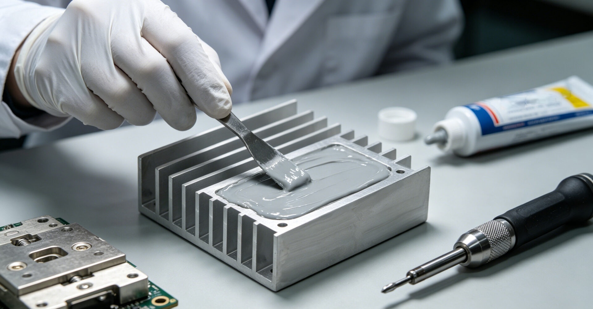
Thermal interface material (TIM) selection is often overlooked but has a disproportionate impact on overall thermal resistance. The interface between a semiconductor case and a heat sink base consists of microscopic air gaps that act as thermal insulators. A properly applied thermal grease, phase-change material, or thermal pad fills these gaps and reduces RthCS from potentially 0.5–1.0 K/W (dry contact) to 0.05–0.2 K/W. For IGBT modules with large mounting surfaces, thermal pads or phase-change materials offer more consistent coverage than grease.
TPS custom aluminum heat sink solutions: extrusion, CNC machining, and integration
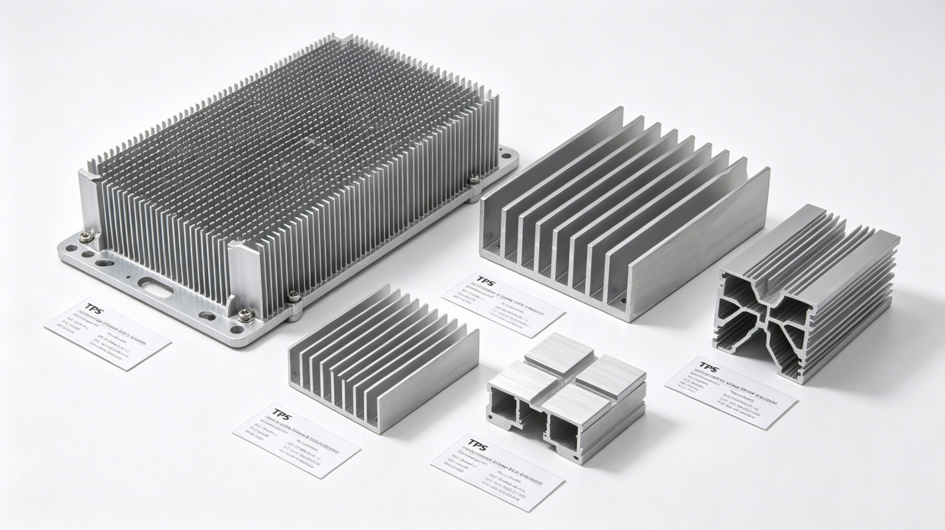
Off-the-shelf heat sinks serve many applications, but high-power IGBT and MOSFET modules often demand custom geometries. Standard heat sink profiles may not match the mounting hole pattern of a specific power module, or they may not fit within the constrained dimensions of an existing enclosure. TPS Elektronik addresses these requirements through a combination of aluminum extrusion and CNC machining capabilities.
Extrusion is the primary manufacturing method for TPS heat sink profiles. The process forces heated aluminum billets through a shaped die, producing long lengths of heat sink with consistent cross-sectional geometry. This method is cost-effective for medium to high volumes and can produce complex fin shapes — straight fins, pin fins, and fluted profiles — that would be impractical with other manufacturing techniques. Standard aluminum alloys include 6063-T5 for optimal extrudability and thermal performance.
CNC machining complements extrusion by adding features that cannot be formed in the extrusion die: precision mounting holes, transistor mounting slots (typically TO-220, TO-247, or TO-3P patterns), cutouts for tall components, and machined flatness on the mounting surface to ensure good thermal contact. For prototype quantities or low-volume production, TPS can machine complete heat sinks from solid aluminum plate, offering maximum geometric freedom without extrusion tooling investment.
TPS offers custom heat sink design and manufacturing through the heat sink product category. The procurement process begins with a review of the thermal requirements, power module specifications, and mechanical constraints. TPS engineers then propose fin geometry, base dimensions, and surface treatment options optimized for the specific application.
Application scenarios: IGBT inverters, MOSFET motor drives, and power supplies
IGBT inverter cooling
Industrial motor drives and renewable energy inverters typically use IGBT modules in half-bridge or six-pack configurations, dissipating 100–500 W per module. These applications demand forced convection cooling with dense fin arrangements and often benefit from custom heat sinks that integrate directly with the inverter enclosure. TPS provides extruded aluminum heat sinks with integrated mounting rails for standard IGBT packages, simplifying mechanical assembly while ensuring uniform clamping pressure across the module baseplate.
MOSFET motor drive cooling
MOSFET-based drives for servo motors, robotics, and EV auxiliary systems often use multiple discrete devices (TO-247 or TO-220 packages) mounted on a shared heat sink. TPS CNC-machined heat sinks can include precisely positioned mounting holes for each device, ensuring consistent thermal contact across all semiconductors. Natural convection designs with widely spaced fins suit lower-power drives in sealed enclosures.
Power supply thermal management
Switch-mode power supplies generate heat in rectifier diodes, switching transistors, and magnetic components. TPS aluminum heat sinks provide cooling for power supply components in both natural and forced convection configurations. See TPS’s aluminum heat sink efficiency analysis for detailed application guidance.
Compliance and standards
Thermal management directly supports compliance with safety standards including IEC 62368-1, which requires that accessible surfaces and components do not exceed specified temperature limits under normal and single-fault conditions. Junction temperature management per IEC 60747-9 ensures that semiconductor devices operate within their rated thermal limits, supporting long-term reliability and regulatory compliance. For additional resources, explore the TPS news and insights section.
RFQ checklist for custom heat sink procurement
To streamline the quotation process, prepare the following information when requesting a custom heat sink from TPS:
- Power semiconductor specifications: Device type (IGBT, MOSFET, SiC MOSFET), package type (module, TO-247, TO-220), quantity of devices per heat sink.
- Thermal requirements: Maximum power dissipation per device (W), maximum ambient temperature (°C), maximum allowable junction or case temperature (°C).
- Cooling strategy: Natural convection or forced convection. If forced, specify available airflow rate (CFM or LFM) or fan specifications.
- Mechanical constraints: Maximum allowable heat sink dimensions (L × W × H in mm), mounting hole pattern or reference module drawing, weight limitations.
- Surface finish preference: Natural, clear anodized, or black anodized.
- Production volume: Prototype quantity, pre-series quantity, and target annual volume for series production.
Frequently Asked Questions
How do I calculate the required heat sink thermal resistance for my IGBT module?
Use the formula RthSA = (Tj_max − Ta) / Pd − (RthJC + RthCS). Obtain RthJC from the IGBT datasheet, estimate RthCS as 0.1–0.2 K/W with proper TIM application, and use your maximum expected ambient temperature and power dissipation. The result is the maximum acceptable sink-to-ambient thermal resistance.
What is the difference between 6063 and 6061 aluminum for heat sinks?
6063-T5 offers higher thermal conductivity (approximately 193–209 W/m·K) and better extrudability, making it ideal for complex fin profiles. 6061-T6 provides greater mechanical strength but slightly lower thermal conductivity (approximately 171 W/m·K). TPS recommends 6063 for most heat sink applications unless structural strength is the primary requirement.
Can TPS provide heat sinks with custom mounting hole patterns for specific IGBT modules?
Yes, TPS offers CNC machining services that add precision mounting holes, slots, and cutouts to extruded or plate aluminum heat sinks. Provide a drawing of the required hole pattern or the IGBT module datasheet during the RFQ process.
What surface finishes are available for TPS aluminum heat sinks?
TPS offers natural (untreated), clear anodized, and black anodized finishes. Black anodizing is recommended for applications where radiative heat transfer is significant, while clear anodizing provides corrosion protection without color change.
Does TPS provide thermal design support or simulation services?
TPS engineers review thermal requirements, recommend heat sink geometries, and can provide calculated thermal resistance values for proposed designs, though formal thermal simulation reports may require separate engineering services during the RFQ process.
Where can I learn more about aluminum heat sink design principles?
Read the TPS technical analysis on aluminum heat sink efficiency and application scenarios or browse the complete heat sink product range.


