In industrial systems such as IPC controllers, compact workstations, storage appliances, and communication equipment, the power supply is more than a basic component.
Electrical noise, start-up behavior, and compliance documentation can influence system stability and project approval timelines. Ripple can affect sensitive I/O electronics, insufficient hold-up time may lead to resets, and missing documentation can delay certification or customer audits.
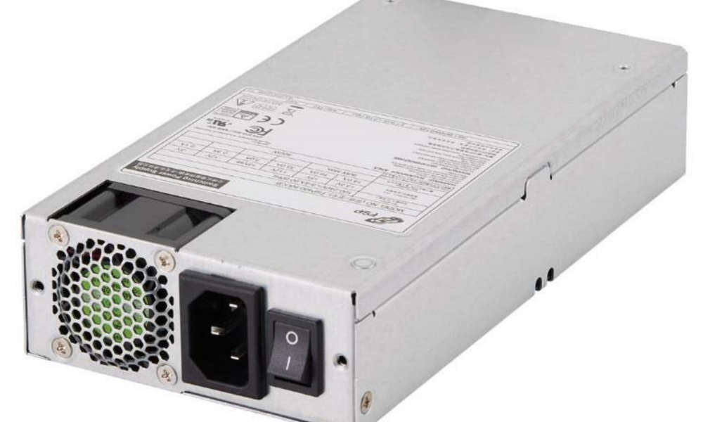
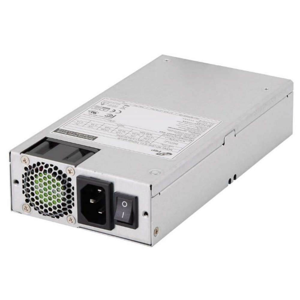
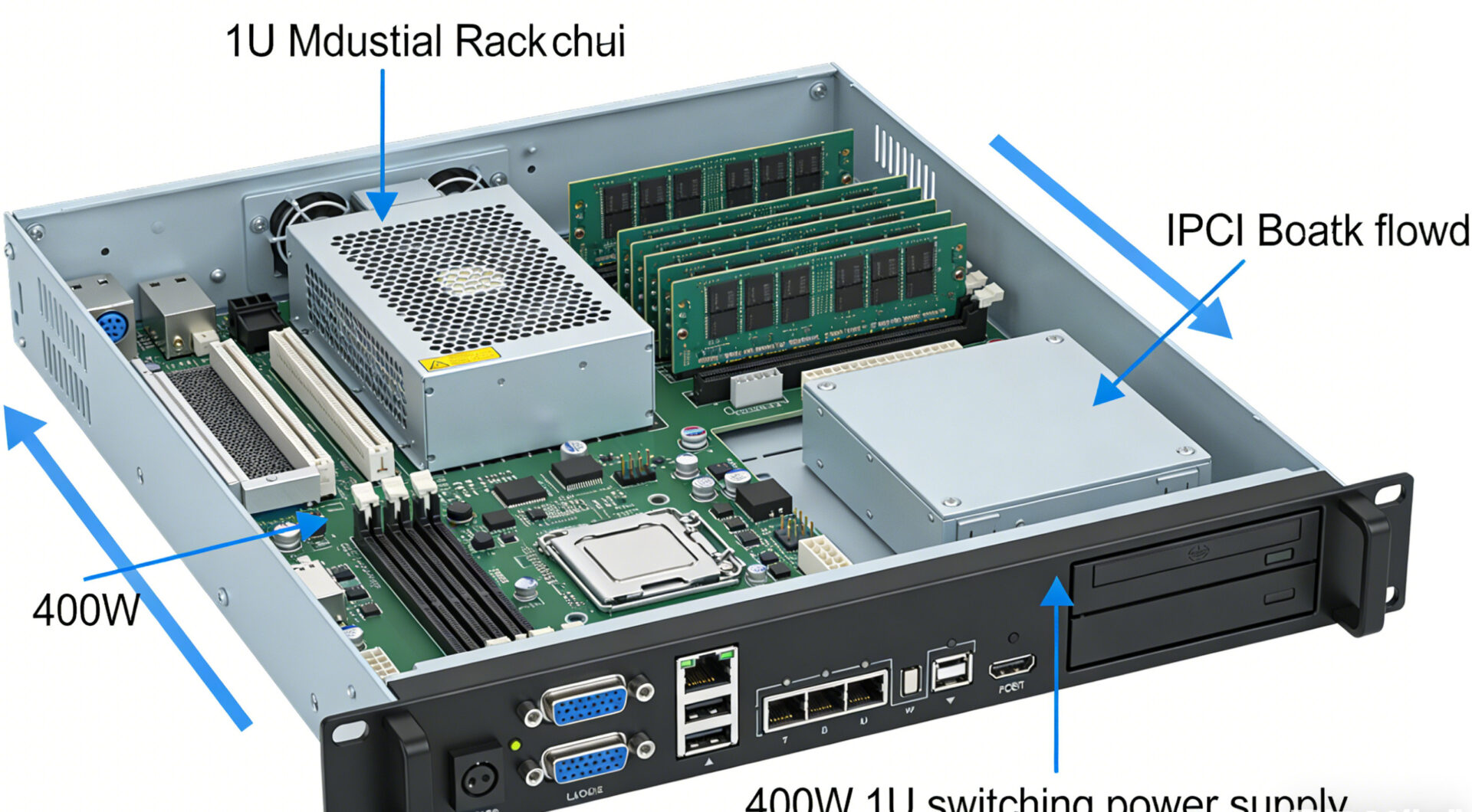
The FSP400-50UCB is designed for integration in 1U rack systems and industrial environments where space constraints, predictable electrical behavior, and documentation availability are relevant for system development and deployment.
Why a 400W 1U Power Supply Matters in Industrial Systems
In many industrial platforms, the power budget is only one design constraint. System engineers must also consider:
Limited mechanical space (1U height restrictions)
Thermal management within dense rack systems
Electrical noise and transient behaviour
Compliance documentation required for customer audits or certification processes
While desktop power supplies may be sufficient for prototypes, production systems typically require predictable behaviour under cross-load conditions, defined start-up signalling, and traceable compliance documentation.
The FSP400-50UCB addresses these requirements with:
Standard 1U industrial form factor
Total output power up to 400 W
Multiple output rails used in industrial ATX platforms
Wide AC input range (90–264 Vac)
The datasheet positions the unit for applications including industrial PCs, workstations, storage systems, and communication platforms.
FSP400-50UCB Overview
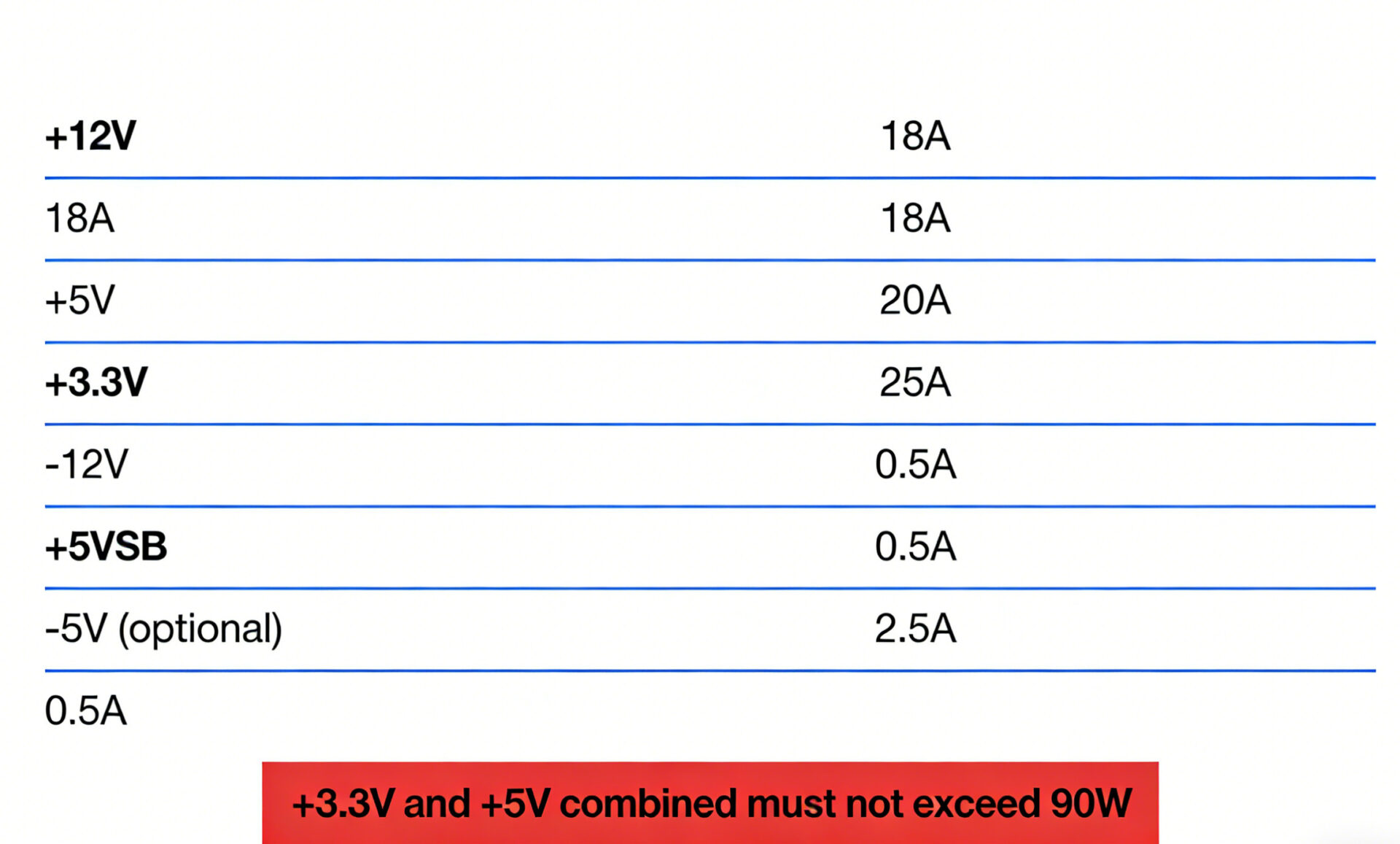
Typical electrical rails include:
+12 V
+5 V
+3.3 V
–12 V
+5 VSB standby rail
optional –5 V
These rails support many ATX-based industrial motherboard and backplane configurations used in IPC and embedded workstation systems.
The specification also includes operating limits such as temperature range and altitude, which are relevant when deploying systems in industrial environments.
Key Electrical Characteristics
Output Rails and Cross-Load Behaviour
In industrial computing systems, the distribution of power between rails can influence stability and compatibility with backplanes or legacy peripherals.
Typical integration considerations include:
+12 V rail: primary supply for CPUs, drives, and PCIe devices
+5 V and +3.3 V rails: often used by legacy I/O and certain controller boards
+5 VSB: supports standby functionality and remote power control
–12 V / optional –5 V: used in some specialised or legacy interfaces
The datasheet specifies that the combined +3.3 V and +5 V output must not exceed 90 W.
System designers should verify cross-load conditions during early design reviews.
Input Range, Efficiency and Inrush Considerations
Industrial installations frequently operate in environments with varying mains conditions, including mixed 115 V / 230 V regions or generator-backed infrastructure.
The FSP400-50UCB supports:
Input range: 90–264 Vac
Frequency: 47–63 Hz
Efficiency: certified according to the 80 PLUS Bronze program
The specification also includes inrush current data, which may be relevant when planning:
circuit breaker sizing
staged start-up sequences
multi-PSU rack deployments
In systems with several power supplies connected to a shared PDU, PS_ON# control logic can help stagger start-up and reduce peak inrush current.
Environmental and Reliability Parameters
The datasheet lists operating conditions typically relevant to industrial equipment.
Examples include:
Operating temperature: 0 °C to 50 °C
Humidity: high relative humidity (non-condensing)
Maximum altitude: up to 5,000 m
The specification also lists an MTBF of 100,000 hours at 25 °C under maximum load conditions.
Manufacturing documentation indicates that units undergo high-voltage (Hi-pot) testing and burn-in procedures, which may be relevant for internal quality documentation or audit narratives.
Compliance and Documentation
For projects involving regulated markets or customer certification processes, documentation availability can be an important procurement factor.
The product documentation references:
CB certification (IEC 62368-1 and IEC 60950-1 frameworks)
RoHS declaration
CE-related documentation
UL documentation references
Mechanical drawings and electrical specifications are also available for integration into project documentation packages.
Integration Considerations for System Designers
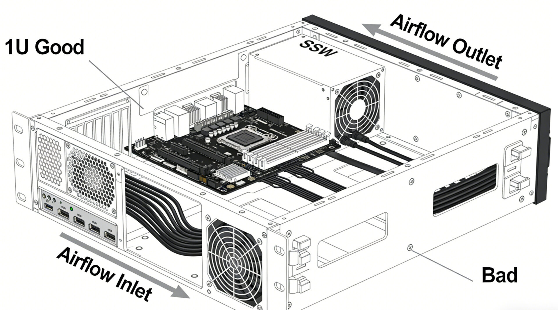
Mechanical Fit and Airflow
1U power supplies operate in thermally dense environments where airflow management is essential.
The FSP400-50UCB dimensions are approximately:
190 × 100 × 40.5 mm
Integration recommendations include:
maintain clear airflow paths around intake and exhaust areas
avoid cable bundles blocking ventilation openings
verify internal chassis temperatures under maximum load
The design uses fan-assisted cooling, typically implemented with a compact internal fan.
Harness and Connector Planning
For system integrators and panel builders, connector configuration and harness routing influence serviceability and assembly consistency.
For procurement reviews, confirm:
required connector types and harness lengths
whether the optional –5 V rail is required
labeling requirements for field maintenance
Including the manufacturer drawing package in production documentation helps ensure consistent cable routing and strain relief during manufacturing.
Controlled Start-Up: PS_ON#, 5VSB and Power-Good
Industrial platforms often rely on controlled start-up sequences.
The specification describes:
PS_ON# control (active-low, TTL compatible)
+5 VSB availability whenever AC input is present
This allows system designers to implement soft start-up logic using supervisory controllers or embedded management systems.
Typical sequence:
standby rail active
environmental checks performed by system controller
PS_ON# asserted to enable main rails
EMI and Grounding Considerations
Achieving low noise at system level depends on both the power supply and the overall system design.
Design review checklist:
avoid ground loops through chassis mounting points
keep high-current loops short
route power harnesses carefully around sensitive analog sections
validate emissions in the final enclosure configuration
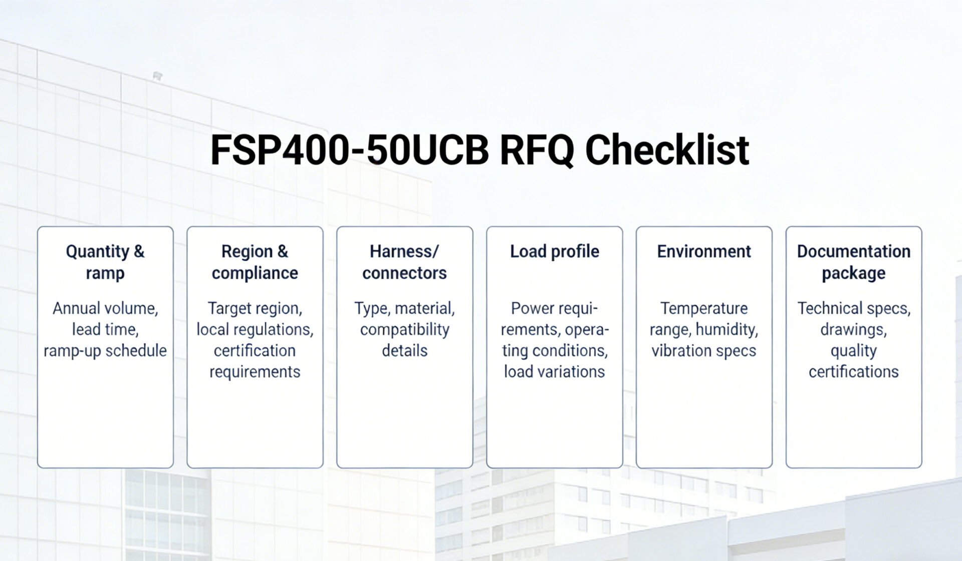
RFQ Checklist for Procurement Teams
To simplify quoting and sourcing, RFQs should typically include:
required quantity and production ramp plan
target region or certification requirements
connector and harness specifications
expected load profile (e.g., peak +12 V current)
environmental conditions such as temperature and altitude
requested documentation packages
Providing these parameters helps suppliers prepare accurate quotations and documentation sets.
Typical Application Scenarios
The FSP400-50UCB may be suitable for systems that require:
Industrial PC Controllers
IPC platforms combining motherboard, I/O cards and communication interfaces often require stable multi-rail power distribution.

Compact Workstations
Engineering workstations and embedded computing systems may require reliable +12 V supply and standby functionality.
Storage and NAS Platforms
Storage appliances typically combine drive arrays and management controllers requiring both main rails and standby functionality.
Communication and Automation Equipment
Equipment deployed in regulated environments may require traceable compliance documentation for integration into finished products.
Alternative TPS Power Supply Options
Depending on system requirements, other power supplies may be considered.
Examples include:
Higher-power IPC systems
Lower-power ATX systems
500 W options
DIN-rail power supplies
Ultra-compact Flex ATX systems
FAQ
Is the FSP400-50UCB suitable for IPC systems?
The model is positioned for IPC controllers, workstations, communication equipment, and storage systems. System designers should confirm cross-load and thermal conditions during system validation.
What does 80 PLUS Bronze indicate?
80 PLUS is a power supply efficiency certification program with defined efficiency thresholds at several load levels. Bronze represents one efficiency tier within this program.
Does the PSU support remote on/off control?
Yes. The specification describes PS_ON# logic and standby rail behaviour, allowing controlled start-up through external system controllers.
Are compliance documents available?
Product documentation typically includes datasheets, mechanical drawings, and compliance declarations accessible from the product page.
How can system-level ripple and noise be minimized?
System designers should apply good grounding practices, short high-current loops, proper airflow management, and validation testing in the final enclosure configuration.


