Imagine your morning coffee maker failing to brew, your smart TV freezing mid-show, or your washing machine stopping mid-cycle. These everyday frustrations often trace back to a small but critical component: the printed circuit board (PCB).
As modern homes incorporate more intelligent devices, expectations for reliability continue to increase. Behind every functional PCB lies a structured testing process. A central element of this process is the needle test adapter, which enables consistent electrical contact during verification.
This article outlines the role of PCB testing and explains how needle test adapters support reliable electronics across a wide range of applications.
Key Takeaways
- Needle test adapters provide mechanical support and electrical contact during PCB testing.
- Designs can be adapted to specific PCB layouts, sizes, and requirements.
- Common materials include phenolic resin (Bakelite) and aluminum profiles.
- Typical applications include electrical testing, functional verification, and fault analysis.
- They are part of a broader ecosystem including ICT fixtures, bed-of-nails systems, and automated test equipment.
1. The Role of PCBs in Modern Electronics
Printed circuit boards form the basis of most electronic devices. They mechanically support components and provide electrical connections via conductive tracks and pads.
Examples:
- Coffee machines: Control heating, pumps, and timing
- Smart TVs: Process signals, manage display and connectivity
- Household devices: Refrigerators, thermostats, and wearables
As device complexity increases, consistent PCB performance becomes essential. Testing helps identify defects before products reach the field.
2. Why PCB Testing Matters
PCB manufacturing involves multiple process steps, including soldering and component placement. Potential defects include:
- Soldering defects
- Misaligned components
- Material inconsistencies
Without testing, such issues may lead to product failures, warranty cases, or rework.
Typical PCB testing includes:
- Electrical testing: Continuity, insulation, component values
- Functional verification: Real-world operation checks
- Troubleshooting: Fault identification and analysis
To perform these tests, the PCB must be securely positioned and electrically contacted. This is achieved using test fixtures and adapters.
3. What Is a Needle Test Adapter?
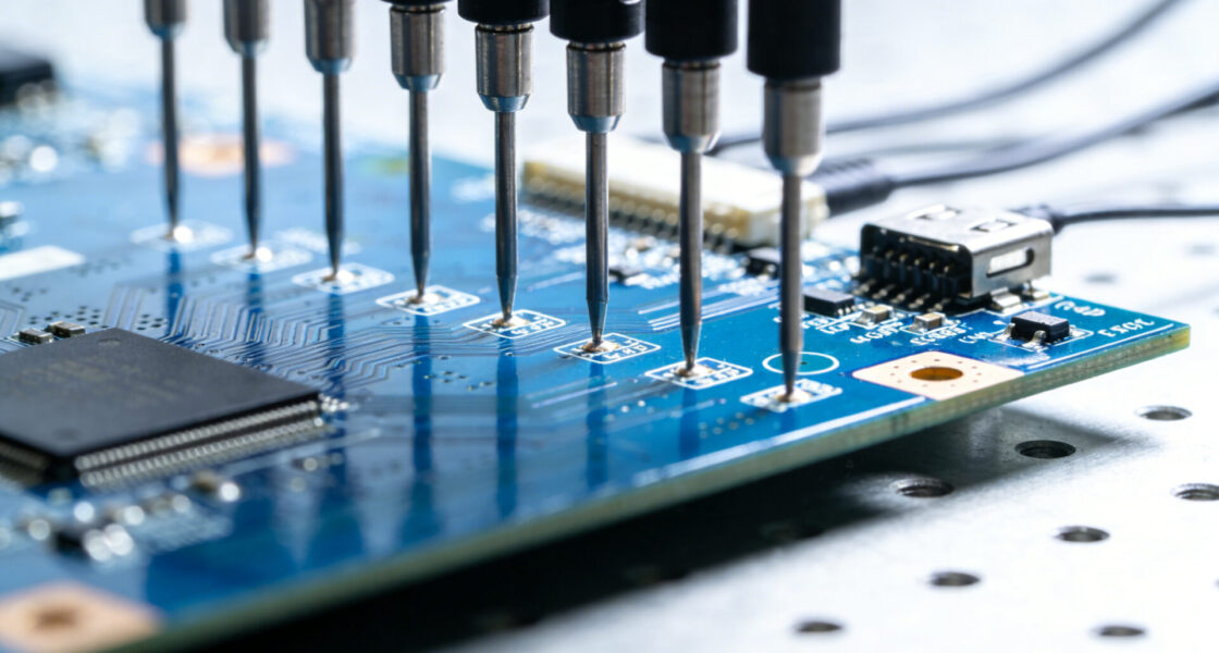
A needle test adapter—often referred to as a bed-of-nails fixture—uses spring-loaded pins to contact defined test points on a PCB.
Key functions:
- Establish reliable electrical connections
- Stabilize the PCB during testing
- Enable repeatable measurements
The pin layout is aligned with the PCB design to ensure consistent contact without damaging pads or components.
4. Key Features of Needle Test Adapters
Customizable Design
Each PCB has unique requirements. Adapters can be tailored in:
- Pin count and layout
- Dimensions
- Mechanical structure
Material Options
- Bakelite (phenolic resin): Good insulation, dimensional stability
- Aluminum profiles: Higher rigidity for larger boards
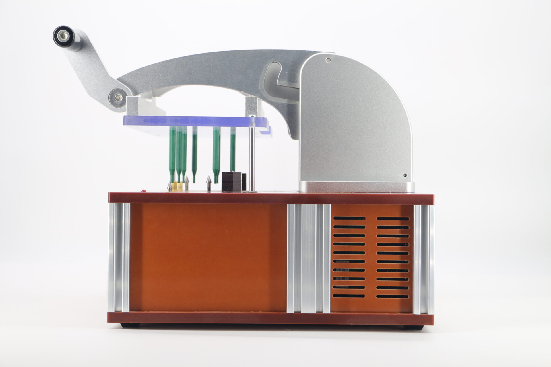
Press-Fit Technology
Pins are inserted into precision-drilled holes using an interference fit. This supports:
- Stable pin positioning
- Consistent contact pressure
- Simplified maintenance (no soldering required)
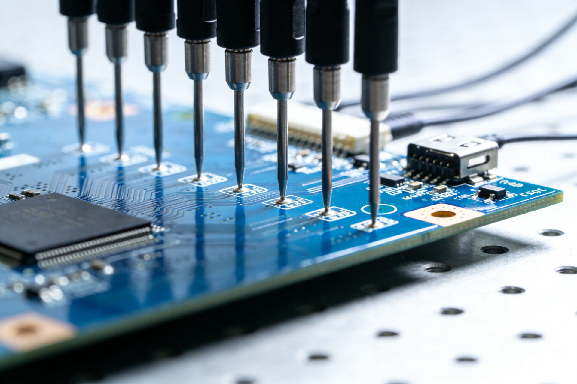
5. Typical Applications
Electrical Testing
The adapter connects the PCB to measurement equipment to verify:
- Shorts and opens
- Resistance and capacitance
- Signal integrity
Functional Verification
The PCB is tested under simulated operating conditions:
- Power is applied
- Signals are injected
- Outputs are monitored
Troubleshooting
Adapters provide access to test points for:
- Oscilloscope measurements
- Signal tracing
- Fault isolation
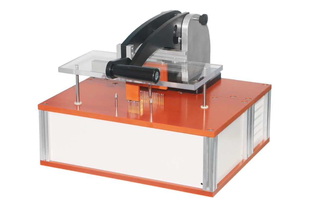
6. Standard Adapter Sizes
Standardized adapters simplify selection for common PCB dimensions.
- BJ9900074: Suitable for smaller boards (up to approx. 150 × 150 mm)
- BJ9900075: Designed for larger boards (up to approx. 300 × 250 mm)
These models are typically integrated into complete test fixtures.
7. PCB Test Fixtures and Systems
Needle test adapters are part of a broader test setup, which may include:
- Base plates and guide systems
- Pneumatic or manual actuation
- Measurement electronics
Common fixture types:
- ICT (In-Circuit Test) fixtures
- Functional test fixtures
- PCBA test fixtures
- Bed-of-nails systems
Test systems range from manual benchtop units to automated machines for high-volume production.
8. Custom Fixture Design Considerations
For complex applications, custom fixtures may be required.
Key design aspects:
- Pin alignment: Matching PCB test points
- Mechanical stability: Preventing board deformation
- Accessibility: Ease of handling and automation
- Durability: Suitability for repeated test cycles
Design is typically supported by CAD modelling and mechanical simulation.
9. Application Examples
Coffee Machine Control Board
A control PCB manages heating, pump control, and user input. Testing may include:
- Electrical verification of power paths
- Functional simulation of brewing cycles
Smart TV Main Board
Complex boards require functional testing under realistic conditions:
- Video and audio processing
- Connectivity interfaces
- Signal validation
In both cases, adapters provide repeatable contact for measurement and diagnostics.
10. Advantages of Needle Test Adapters
- Consistent contact: Spring-loaded pins support stable measurements
- High throughput: Multiple test points contacted simultaneously
- Non-destructive: Designed to avoid PCB damage under normal use
- Flexible design: Adaptable to different PCB types
- Reusable: Suitable for repeated production testing
11. Selection Criteria
When selecting a needle test adapter, consider:
- PCB dimensions and thickness
- Number and spacing of test points
- Required materials (insulation vs. rigidity)
- Environmental conditions (temperature, humidity)
- Compatibility with existing test systems
Supplier support may assist with selection or custom design.
12. Trends in PCB Testing
PCB testing continues to evolve alongside increasing product complexity.
Relevant developments include:
- Integration with AOI and X-ray inspection
- Increased automation
- Use of advanced materials for fixtures
Despite these trends, needle test adapters remain widely used in electrical and in-circuit testing applications.
Conclusion
From household appliances to complex consumer electronics, PCB functionality is essential for reliable operation. Structured testing processes help identify defects early in production.
Needle test adapters provide a practical interface between PCBs and test systems. With adaptable designs, established materials, and repeatable contact mechanisms, they remain a key component in many testing environments.
Selecting the appropriate adapter and fixture concept depends on application requirements, production volume, and system integration.


