A German automotive Tier 1 supplier faced a critical project milestone: their 48 V to 12 V DC-DC converter for an electric vehicle platform had to pass CISPR 25 Class 5 conducted emissions. The most stringent automotive EMI standard. Initial pre-compliance testing at TPS Elektronik’s EMC laboratory revealed excessive noise across the AM and FM broadcast bands, with peaks exceeding Class 5 limits by more than 10 dBμV. The root cause? A poorly implemented split ground plane and suboptimal common mode choke placement that turned the PCB into an unintentional antenna.
This case study documents how our engineering team guided the customer through targeted layout modifications—ground plane stitching, choke repositioning, and filter network optimization. Which to achieve CISPR 25 Class 5 compliance without a costly board respin. For system integrators, panel builders, and electrical engineers facing similar challenges, the lessons learned offer a practical roadmap for automotive EMC success with EMC layout guidelines.
1. The Challenge: CISPR 25 Class 5 Conducted Emissions Failure
The customer—a German automotive Tier 1 supplier—approached TPS Elektronik with a problem. Their 48 V to 12 V DC-DC converter, designed for an electric vehicle platform. Which had failed conducted emissions testing at an accredited laboratory. The project was behind schedule, and a second failure would trigger a mandatory board redesign. Which costing hundreds of thousands of euros in tooling and validation delays.
CISPR 25 Class 5 is the most stringent automotive EMI standard, with limits designed to protect vehicle receivers from disturbances generated by electronic components and modules. Conducted emissions measured from 150 kHz to 108 MHz using a Line Impedance Stabilization Network (LISN) inserted between the power supply and the Device Under Test (DUT). The standard defines five classes, with Class 5 being the most demanding—peak limits in the FM broadcast band (76–108 MHz) are just 38 dBμV.
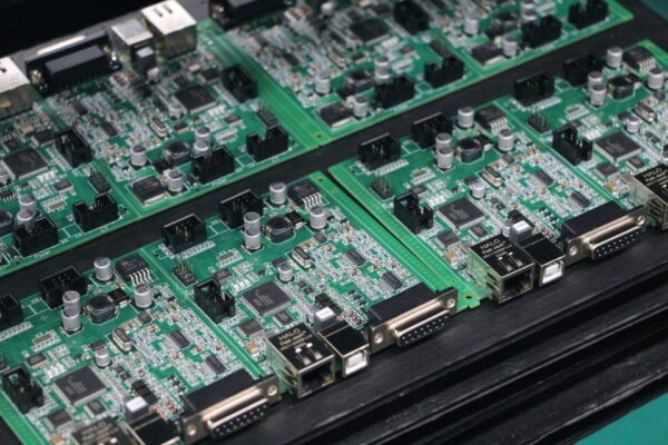
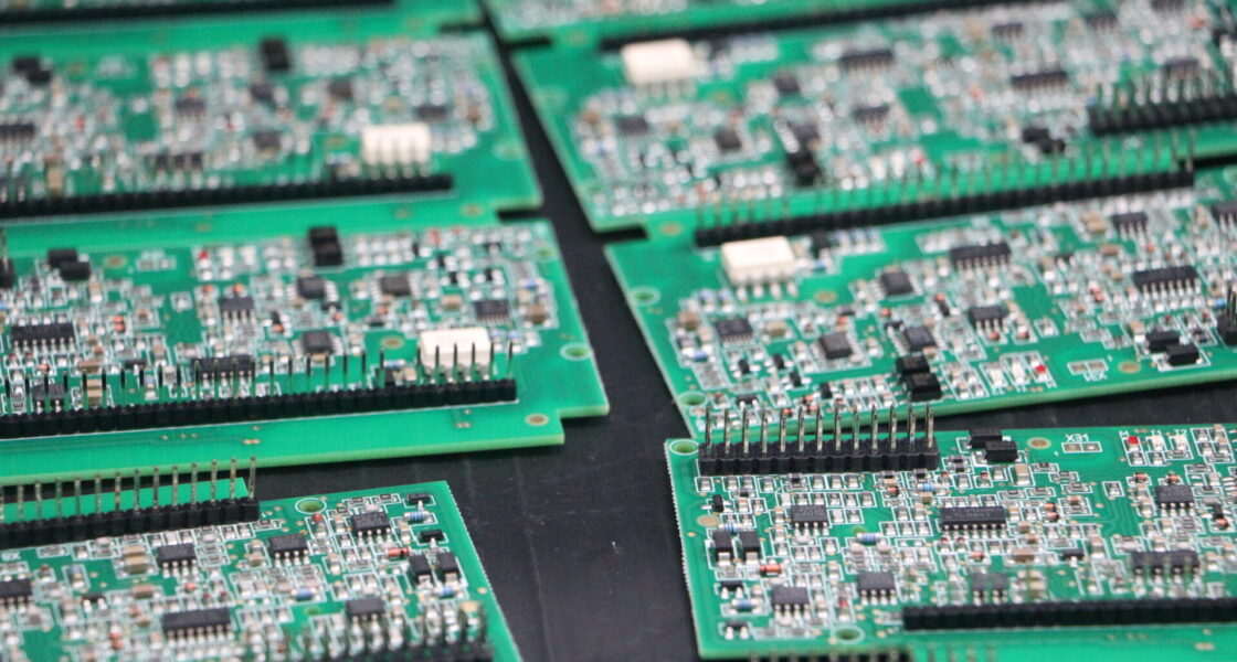
The customer’s design used a 4-layer PCB with a split ground plane intended to isolate the noisy digital/power domain from the sensitive analog circuitry. A common mode choke placed at the DC input to filter conducted noise. Yet emissions at 80–90 MHz consistently exceeded the Class 5 average limit by more than 10 dBμV.
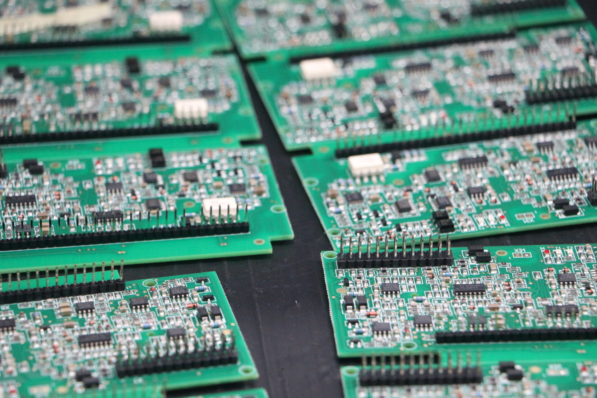
TPS’s EMC laboratory services engaged to perform root-cause analysis and pre-compliance testing. Our team brought the DUT into our Shanghai-based EMC laboratory, which equipped to conduct CISPR 25 pre-compliance measurements using calibrated LISNs, spectrum analyzers, and a CISPR 16-1-1 compliant measuring receiver.
2. Split Ground Plane: The Hidden Antenna
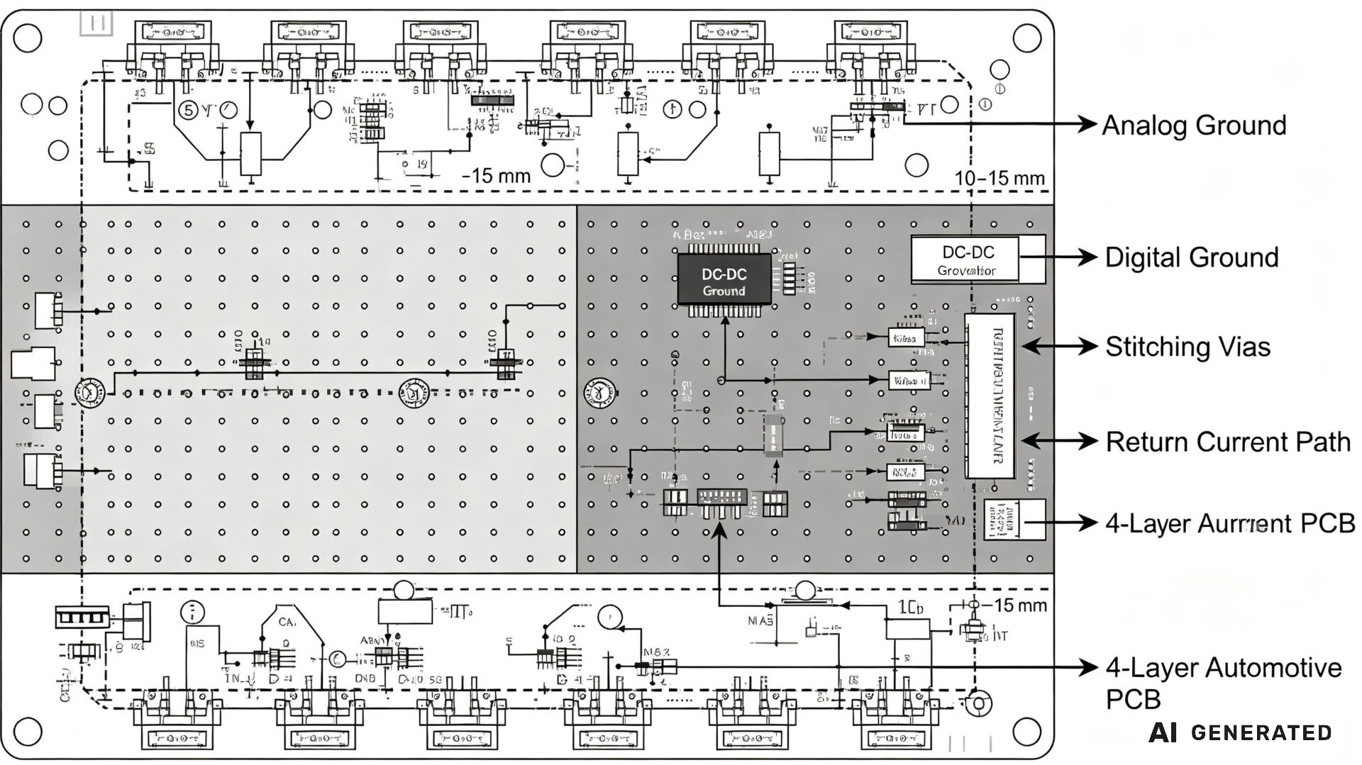
Our first diagnostic step was a near-field scan of the PCB. The results were revealing: emissions concentrated around the boundary between the digital/power ground plane and the analog ground plane. The split in the ground plane—intended to isolate noisy digital currents from sensitive analog circuits. Which had created an impedance discontinuity.
At frequencies above 100 MHz, the slot formed by the split ground plane acts as an effective antenna. High-frequency return currents, unable to flow directly beneath their signal traces. Which forced to find alternative paths around the split boundary. These detours create large loop areas that radiate electromagnetic energy.
In automotive mixed-signal PCBs, a solid, uninterrupted ground plane with disciplined component placement typically outperforms split ground architectures. However, when isolation between analog and digital domains absolutely required, the split must managed carefully:
- Stitching vias must placed at intervals of 10–15 mm along the split boundary to provide high-frequency return current paths.
- Signal traces must not cross the split—any trace that crosses a ground plane split forces its return current to find a longer path, creating a radiating loop.
- High-speed signals (CAN, automotive Ethernet, LVDS) should routed over a continuous ground plane with controlled impedance.
Our analysis revealed that the customer’s PCB had stitching vias spaced at 40–50 mm—far too wide for effective high-frequency return current management. Moreover, a critical clock signal trace crossed the split boundary. Which creating a significant radiating loop at its harmonic frequencies.
TPS’s EMC testing guide provides additional detail on ground plane design principles. Our EMC testing customer case studies illustrate how we have solved similar issues for other automotive clients.
3. Common Mode Choke Placement: Proximity Matters
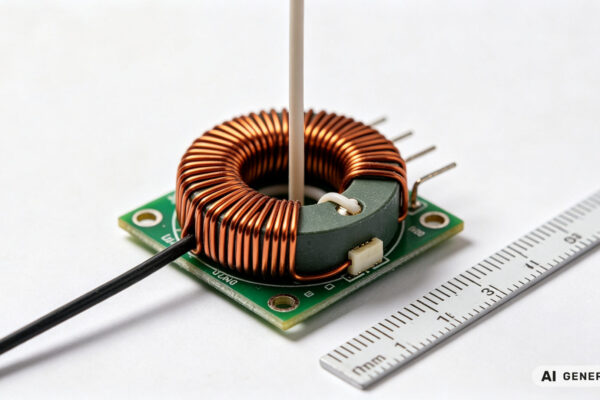
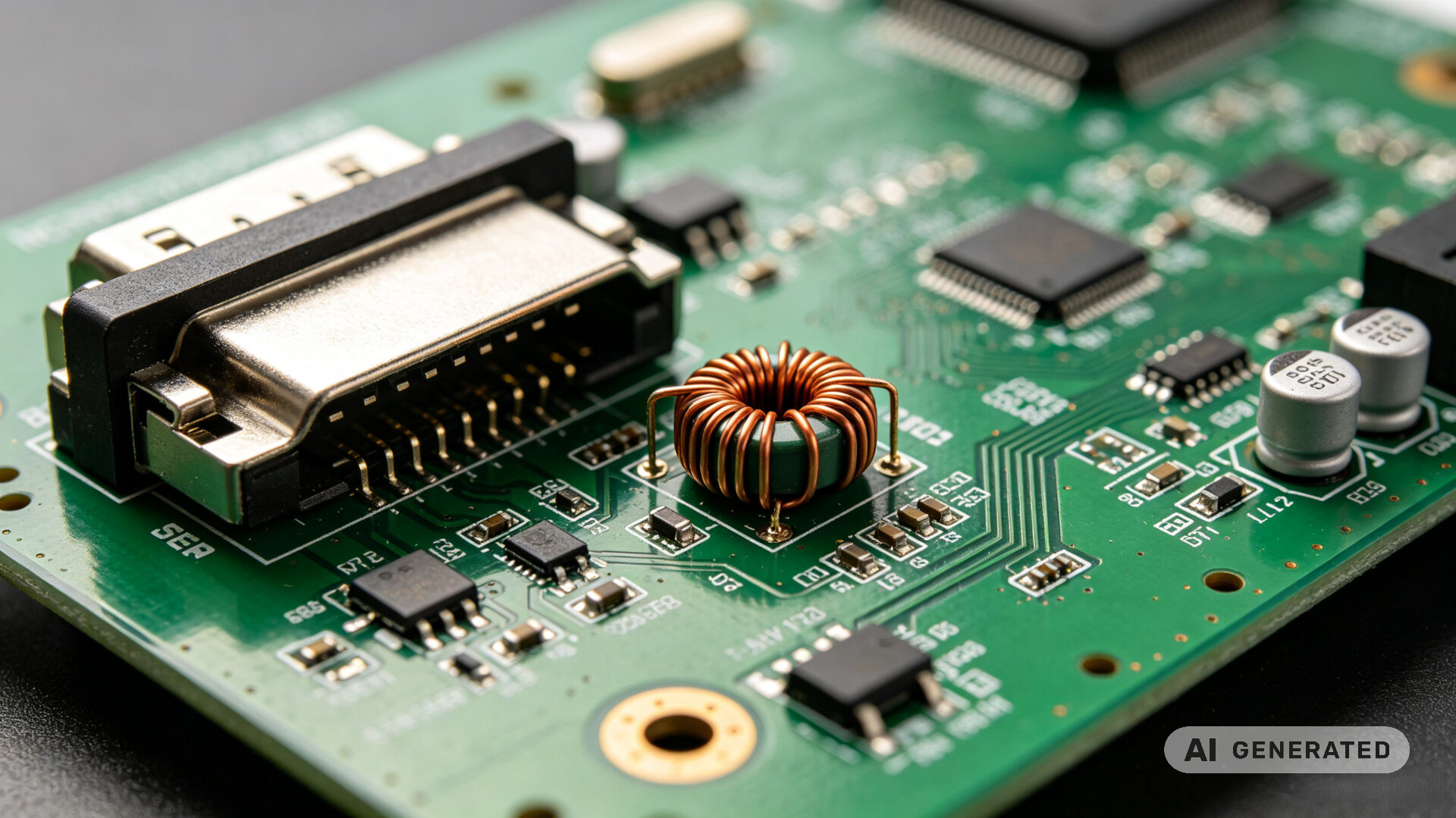
The second issue identified during our pre-compliance testing was the placement of the common mode choke at the DC input. A common mode choke designed to suppress common mode noise—unwanted currents that flow in the same direction on both the power and return lines. It allows differential signals to pass while presenting high impedance to common mode noise.
However, the effectiveness of a common mode choke depends critically on its placement on the PCB. The choke must be placed as close to the I/O connector (the source or exit point of the noise) as physically possible. If placed too far “inland,” the PCB traces between the connector and the choke act as antennas, radiating noise before it reaches the filter.
In the customer’s design, the common mode choke located more than 30 mm from the DC input connector. The intervening traces—approximately 30 mm of copper on the PCB. Which radiating conducted noise at 80–90 MHz, explaining the persistent emissions peak.
Additional optimization opportunities identified:
- Filter capacitors (both differential-mode and common-mode) should placed on both sides of the choke.
- Ferrite beads on power lines can provide additional high-frequency attenuation.
- Minimize the loop area of the input power path—the distance between the power trace and its return path should be as small as possible.
For automotive DC-DC converters, the conducted EMI noise in the 150 kHz to 30 MHz range primarily comprised of switching frequency harmonics. Above 30 MHz, near-field radiation becomes dominant and EMI filters become less effective due to parasitic capacitance and inductance. Which making layout optimization even more critical.
TPS’s EMC compliance guide and EMC and electrical safety testing resources offer comprehensive guidance on filter placement and PCB layout for automotive applications.
4. The Pre-Compliance Advantage: Catching Issues Early
This case study illustrates why pre-compliance testing is essential for automotive electronics development. Formal CISPR 25 testing at accredited laboratories is expensive and time-sensitive. A single failure can cost thousands in re-test fees and weeks in schedule delays.
TPS Elektronik’s EMC laboratory services structured to reduce this risk. Our pre-compliance approach includes:
- Early-phase EMC measurements on prototypes before formal testing.
- Design-for-EMC guidance during the PCB layout phase.
- Root-cause analysis of emissions failures, identifying specific layout issues.
- Structured test reports documenting findings and recommended mitigations.
Our laboratory equipped to perform CISPR 25 conducted and radiated emissions testing, as well as immunity testing per ISO 11452 and ISO 7637. We support automotive, industrial, medical, and consumer electronics applications.
For this customer, the pre-compliance testing identified the split ground plane and common mode choke placement issues in a single day. The recommended modifications—adding stitching vias, relocating the choke, and rerouting the clock signal. Which implemented in the next PCB revision. The customer returned for a second round of pre-compliance testing, confirming that emissions were now well below Class 5 limits.
5. Results: Passing CISPR 25 Class 5 with Layout Optimizations
The customer implemented the following modifications based on our recommendations:
- Ground plane stitching: Added stitching vias at 12 mm intervals along the split boundary, providing high-frequency return current paths.
- Common mode choke relocation: Moved the choke to within 5 mm of the DC input connector, minimizing the radiating trace length.
- Clock signal rerouting: Rerouted the critical clock signal over a continuous ground plane, eliminating the split crossing.
- Additional filter capacitors: Added 100 nF and 1 nF capacitors on both sides of the common mode choke for differential and common mode filtering.
After the modifications, the customer returned to TPS’s EMC laboratory for a second round of pre-compliance testing. The results were conclusive:
- Emissions at 80–90 MHz reduced by more than 15 dBμV.
- All frequency bands were now at least 6 dB below the CISPR 25 Class 5 average limits.
- The design passed formal CISPR 25 conducted emissions testing at the accredited laboratory on the first attempt.
The customer avoided a costly board redesign and met their project deadline. The total cost of the TPS pre-compliance testing and consulting services was a fraction of the cost of a single formal certification failure.
For more automotive EMC case studies, see our combined EMC and electrical safety testing case and EMC testing collaboration case.