

System integrators, panel builders, and procurement teams rarely lose a sealing qualification because the drawing is wrong. They lose it when the first batch seals perfectly and the third batch leaks, when the O-ring groove measures inside tolerance on the bench but the seal fails in a pressure test. Or when the surface finish on the seal face is “Ra 0.8” on the certificate and something else on the part.
A European sensor manufacturer (name withheld under NDA) brought exactly that problem to TPS: a 316L stainless connector body with an O-ring face seal, specified to tight groove tolerances. That passed first article and then produced intermittent leaks in series production. TPS’s precision machining services used to re-establish a controlled turning process—tool strategy, in-process gauging, surface texture specification and SPC—so that the sealing surface became repeatable rather than occasionally correct.
1. The challenge: a seal that passes first article and fails in series
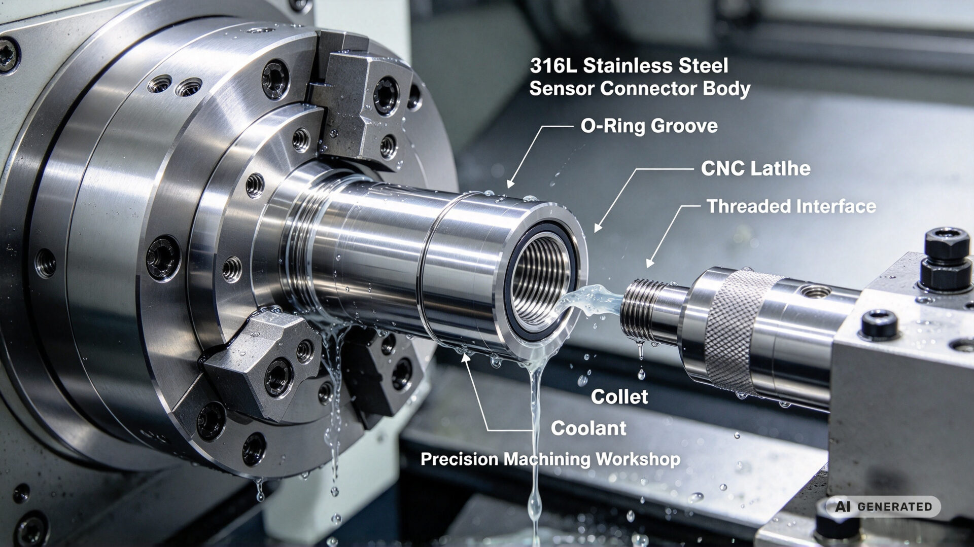
The part was a 316L stainless connector body, roughly 28 mm long, with an external thread on one end, a hexagonal wrench flat in the middle. And an O-ring groove on a cylindrical sealing face at the other end. The seal was static, radial, against a mating bore in the sensor housing.
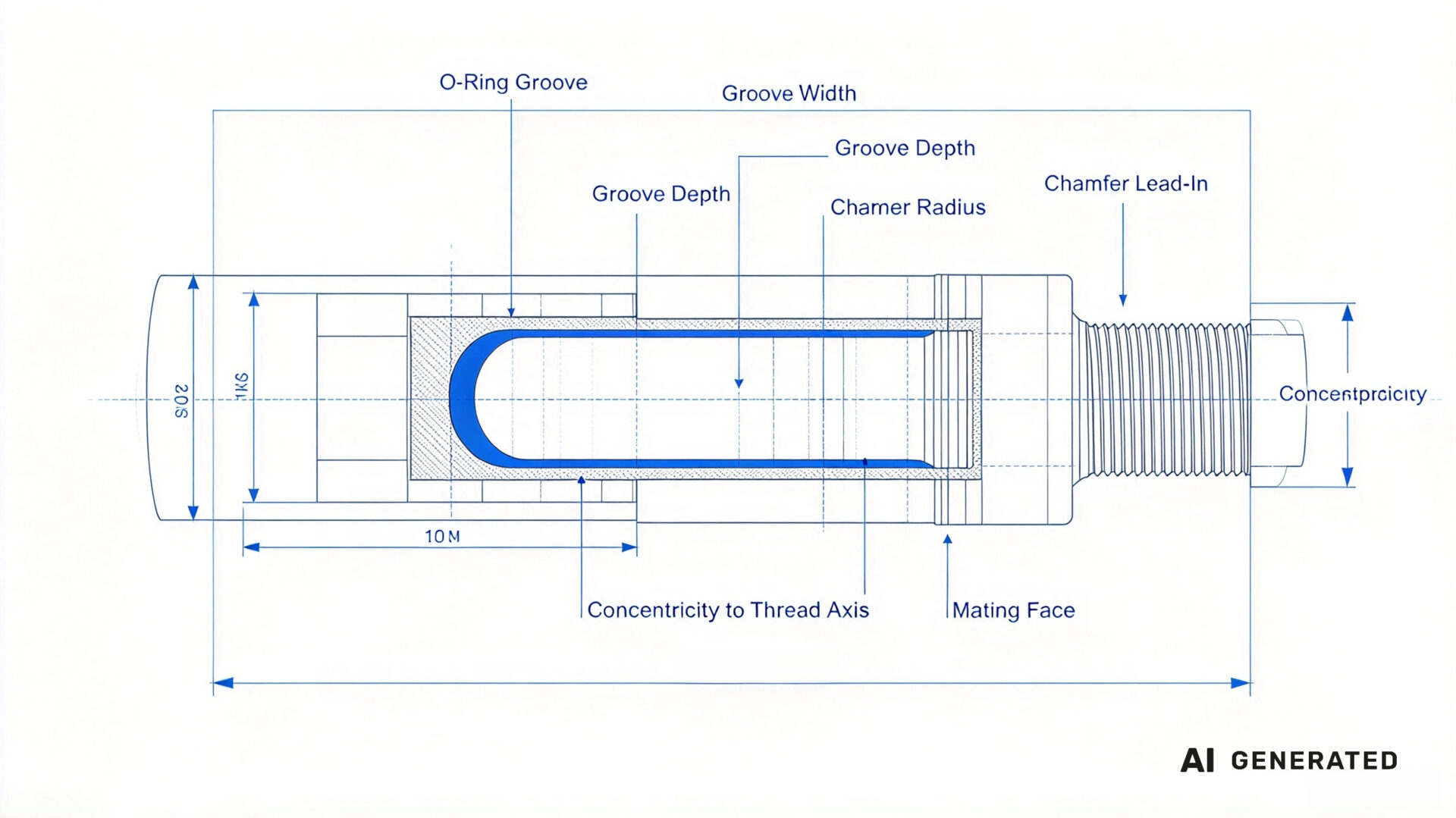
The drawing specified the groove width and depth to general tolerances, a concentricity of 0.03 mm between the groove diameter and the thread axis. And a surface finish of Ra 0.8 µm on the seal face. First article passed. Two months into series production, roughly 4% of parts leaked in the pressure test. And the leak rate not correlated with any single measured dimension.
That pattern—dimensions in tolerance, seal still failing—is the classic signature of a sealing surface that is not repeatable. The measurement the drawing asked for was satisfied. The characteristic that actually controls sealing not specified, not measured, or not controlled.
2. What makes a turned sealing surface repeatable
A static O-ring seal on a turned stainless face depends on four things that the drawing often treats as secondary: groove geometry relative to the seal cross-section, concentricity of the groove to the mating axis, the surface texture in the seal contact band, and the absence of burrs or tool marks that cross the seal path.
2.1 Groove geometry and concentricity
O-ring groove dimensions defined by ISO 3601-1 for the O-ring itself and by the groove design guidance that accompanies it. For a radial static seal, the groove width must allow the elastomer to fill the space without over-compressed. And the groove depth must produce the specified squeeze—typically 15–25% for static radial seals. A groove that is 0.02 mm too shallow increases squeeze and can cause extrusion or accelerated compression set.
Concentricity matters because a radial seal tolerates a certain eccentricity but not an unlimited one. If the groove diameter is offset from the thread axis, the squeeze is uneven around the circumference: one side is over-compressed, the other under-compressed. The under-compressed side is where the leak starts. This is why the concentricity callout in the example above—0.03 mm—correct in principle but insufficient without controlling how it produced and measured.
2.2 Surface texture: Ra is not enough
Ra 0.8 µm is an average roughness value. It says nothing about the direction of the tool marks, the peak-to-valley height (Rz), or the waviness of the surface. A turned surface has circumferential tool marks; if the seal contact band runs across those marks, the elastomer can bridge them, but if the marks are deep enough, the seal cannot fill them and a leak path remains.
For elastomer seals, the practical specification is a combination: Ra below the specified limit, Rz below a defined value, and a texture direction that follows the seal path rather than crossing it. ISO 4287 defines the parameters (Ra, Rz, Rmax) and the evaluation length. So the specification is meaningful only if the measurement conditions also stated. “Ra 0.8” without a cutoff length and a measurement direction is an incomplete requirement.
2.3 Edges, burrs, and the seal path
The groove entry chamfer and the groove corner radii are part of the seal path. A sharp corner cuts the O-ring during assembly; a burr at the groove edge creates a leak path that no amount of groove accuracy can close. Deburring must be a controlled process step with a defined method and a verification, not an operator judgement at the end of the cycle.
3. How TPS converted the process into a controlled one
The corrective action was not a design change. It was a process change: the same part, produced with a defined tool strategy, in-process measurement, and a surface specification that actually controls the seal.
3.1 DFM and drawing review
The review identified three gaps in the drawing: the groove width and depth toleranced against the nominal O-ring rather than against the ISO 3601 groove table, the surface specification did not state Rz or the measurement cutoff, and the deburring method not defined. TPS proposed a revised specification with the groove dimensions tied to the O-ring cross-section, a combined Ra/Rz requirement with a stated evaluation length, and a defined edge treatment.
3.2 Tool strategy and in-process gauging
The groove finished in a single pass with a dedicated grooving insert, using the same tool and the same feed for every part, rather than being produced by a combination of turning and parting operations. Tool wear compensated by indexing at a defined interval, and the first part after each index was measured.
In-process gauging measured the groove diameter and the concentricity at the machine, before the part released from the collet. Measuring after release catches the error too late; measuring while the part is still clamped allows a correction on the same setup. This is the same logic that TPS applies to tight-tolerance prototypes, described in the precision CNC machining resource.
3.3 Verification and SPC
Every batch received a first-article measurement on a coordinate measuring machine and a surface texture measurement on the seal band. During production, groove diameter and concentricity recorded on a control chart, and the process stopped when a trend appeared—not only when a limit was exceeded. The prototype-to-production guide describes how this control plan is transferred from the sample to the series.

4. Measured outcome
The revised process reduced the leak rate from roughly 4% to below 0.2% over the following three production lots, and the remaining rejects were traceable to the mating housing, not the turned connector. Groove concentricity moved from a spread of about 0.04 mm to a spread of about 0.015 mm. And the surface texture on the seal band met both the Ra and Rz limits with margin.
The durable result not the corrected batch. It was the specification: the drawing now states the groove dimensions against the O-ring table, the surface texture with the measurement conditions, and the edge treatment. That specification is what made the seal repeatable across suppliers—and it is the part that procurement can hold a future source to.

5. RFQ checklist
To streamline quotation and process review for a cnc turning supplier engaged on a stainless sealing component, provide:
- Drawing with the O-ring callout: O-ring size and standard, groove dimensions tied to the groove table, not only to a nominal
- Concentricity requirement: Which axis is the datum, and the allowable eccentricity of the groove
- Surface specification: Ra and Rz limits, evaluation length, cutoff, and measurement direction
- Edge treatment: Chamfer or radius at the groove entry, deburring method, and any burr limit
- Material and condition: 303, 316L, or other grade, bar stock, and any passivation requirement
- Sealing function: Static or dynamic, radial or face seal, pressure, and media
- Verification: First-article report, surface texture record, and whether SPC data required
- Volume: Prototype, pilot, and series quantities with delivery milestones
Providing these details reduces clarification cycles. TPS’s engineering team can support groove specification, surface texture definition. And the control plan as part of the RFQ process.