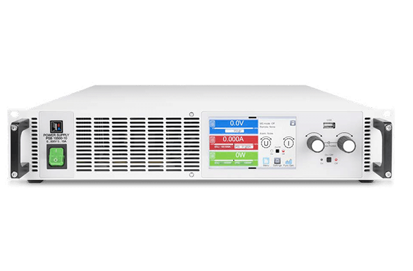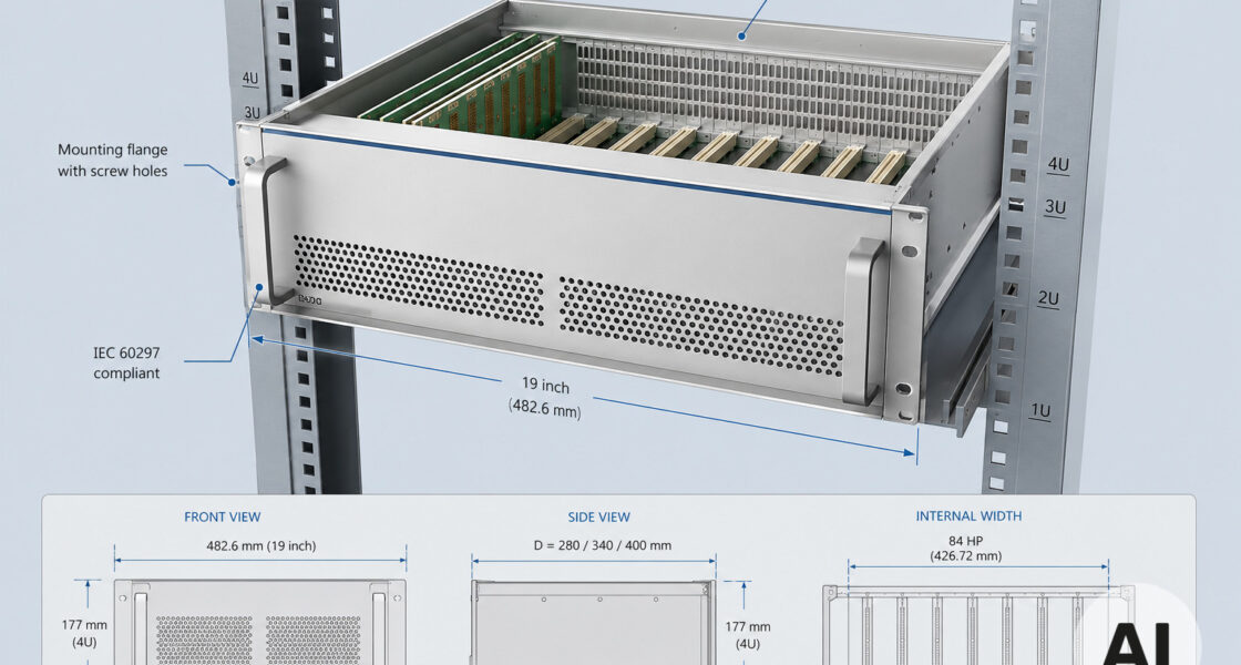
European hardware engineers rarely find a one-size-fits-all 19 inch chassis. The 19″ rackmount chassis remains the backbone of industrial, laboratory, telecom and instrumentation systems. However, your choices on height, depth, mounting and standard compliance directly affect thermal performance, EMC behaviour, serviceability and certification.
A 19 inch rack mount chassis based on IEC 60297 dimensions gives you a reliable starting point. Yet many projects require a 19″ rack chassis that goes beyond catalogue dimensions. For example, you may need a 1U chassis for a shallow network appliance, a 6U chassis for a high-capacity VME or VPX system, or a half-rack chassis for a compact installation. Therefore, the mechanical platform must match both the board architecture and the operating environment. This guide explains how to select from a standards-first perspective. Moreover, it shows when to move from a standard 19″ enclosure or 19 inch rack enclosure to a customised rackmount enclosure with modified depth, cutouts and structural reinforcement.
As a supplier with in-house design and manufacturing capability, we help European engineers move from off-the-shelf 19″ rackmount chassis and DIN 41494 chassis platforms to application-specific solutions. Rather than forcing a standard part into a non-standard requirement, we use proven IEC 60297 building blocks to create a 19 inch rack mount chassis that fits your exact board set, cooling strategy and integration constraints. Furthermore, we support the mechanical design process from initial CAD review to prototype and series production, so you are never locked into a fixed catalogue part.
Why the 19-Inch Standard Remains the Default for European Rack Systems
IEC 60297 and DIN 41494 define the 19-inch form factor. In addition, IEEE 1101.10 adds card-level details. These standards define the critical interfaces that allow boards, front panels, backplanes and subracks from different manufacturers to work together. As a result, a 19 inch rack enclosure built to these dimensions gives you predictable mounting hole positions, front panel widths and card depths. That predictability is why a 19″ rackmount chassis or 19″ rack chassis is still the default for so many European projects. For instance, you see them in lab instruments and railway signalling.
Compliance with IEC 60297 does not make every 19″ enclosure identical. The standard allows variation in depth, internal layout and panel design. A standard 19 inch rack enclosure may work well for a simple test system. However, a high-power telecom chassis or a ruggedised industrial rackmount enclosure often requires additional mechanical work. Our role is to help you decide what to take from a standard platform and what to customise.
- IEC 60297 chassis — defines the basic 19-inch width, mounting flange dimensions and U-height spacing
- DIN 41494 chassis — closely related standard for Eurocard-based subracks and plug-in units
- IEEE 1101.10 chassis — adds front panel, handle and injector/ejector details for card-based systems
- Rackmount enclosure — a general term covering enclosed 19-inch units for electronics
Starting from these standards avoids reinventing the mechanical interface. Nevertheless, the real engineering work lies in details the standards do not fully prescribe. These include internal airflow, rear I/O access, environmental sealing and mounting for specific backplanes. Consequently, that is where a knowledgeable 19″ chassis partner adds value.
Height Is Not the Only Variable: Typical Applications from 1U to 6U
Height is the first parameter most engineers specify. A 1U chassis offers 44.45 mm of vertical space, which suits compact network appliances and shallow controllers. A 2U chassis doubles that to 88.90 mm and provides room for low-profile cards and larger power supplies. Meanwhile, a 3U chassis is the classic choice for many Eurocard-based systems, including CompactPCI and PXI, because it accommodates 100 mm deep cards. A 4U chassis often handles high-performance storage or server-style applications. Similarly, a 6U chassis gives the 160 mm card depth required by many VMEbus and VPX systems. Finally, a half-rack chassis, with a width of about 210 mm, works when a full 19″ rack chassis is not required.
- 1U chassis — ideal for slim network appliances, patch panels and shallow-depth controllers
- 2U chassis — balances card access and internal volume for small servers and industrial PCs
- 3U chassis — the default for CompactPCI, PXI and many Eurocard-based instruments
- 4U chassis — provides additional space for storage arrays, high-wattage power supplies and cable management
- 6U chassis — required for 160 mm deep cards used in VMEbus, VPX and some high-power telecom systems
- Half-rack chassis — a space-saving alternative when full rack width is not necessary
Height is not the only variable. Two different 3U chassis can behave very differently. Depth, airflow and panel design all influence behaviour. For example, a 3U chassis for a benchtop instrument may be only 200 mm deep. In contrast, a 3U chassis for a railway computer may need 350 mm depth to accommodate a backplane and rear transition modules. That is why we evaluate the complete mechanical envelope, not just the front panel height.

Depth, Mounting and Serviceability: Slide Rails, Handles and Front/Rear Panels
Depth often ranks second in importance after height. A shallow 19″ rackmount chassis suits wall-mounted or desktop use. On the other hand, a deep 19 inch rack mount chassis may house a full-size backplane, long cards and rear transition modules. The 19″ rack chassis must also provide the correct mounting interface. Front mounting flanges are standard, but many systems also benefit from rear support brackets or telescopic slide rails. Slide rails improve serviceability because they allow the whole enclosure to be pulled forward while still connected to power and signal cabling.
Handles on the front panel are not just cosmetic. They provide a safe grip during insertion and removal. Additionally, they can act as a mechanical stop to prevent over-insertion into a rack. A 19″ rackmount chassis with front panel and handles is easier to service in the field, especially in railway or telecom environments with short maintenance windows. The front panel itself can be blank, perforated for airflow, or CNC-machined with specific cutouts for connectors, displays and indicators.
- Slide rails — allow the chassis to be extended from the rack without disconnecting cables
- Front handles — improve ergonomics and reduce the risk of connector damage during installation
- Rear I/O panel — provides a dedicated area for connectors, bulkhead feedthroughs and cable strain relief
- Ventilation pattern — perforations or slots that balance airflow with EMC shielding and structural stiffness
We recommend that European engineers define the service approach before finalising the mechanical design. If a system must be swapped within five minutes in a telecom rack, slide rails and quick-release handles are essential. Conversely, if the enclosure will never be touched after installation, a simpler fixed-mount 19″ enclosure may work. These decisions directly affect cost, lead time and long-term reliability.
Beyond the Standard: When IEC 60297 Is Not Enough
A standard IEC 60297 chassis or DIN 41494 chassis gives you a defined width and mounting interface. But many projects require modifications beyond catalogue offerings. A 19 inch rack enclosure may need a custom depth to match a specific backplane or a non-standard rear transition area. Similarly, a 19″ rackmount chassis may require additional cutouts for specialised connectors, RF feedthroughs or fibre-optic bulkheads. Sometimes the enclosure must withstand shock and vibration profiles that generic sheet metal designs cannot handle.
These are not rare requirements. Railway applications often demand stiffened side plates and reinforced mounting flanges to meet EN 50155 vibration tests. Medical systems may require smooth, cleanable surfaces and specific materials for biocompatibility or chemical resistance. Outdoor installations may need additional sealing and condensation management. Even a simple 19″ rack case for a laboratory instrument may need a custom front panel cutout and a rear I/O layout that matches a specific PCB design.
We find that the most efficient approach is not to start from a blank sheet. Instead, we take a proven standard 19″ enclosure platform and modify it in a controlled way. This keeps the mounting interface, card guides and panel geometry consistent with IEC 60297. Moreover, it allows you to tailor depth, cutouts and reinforcement to the application. As a result, you get a rackmount enclosure that behaves like a standard product but fits like a custom design.
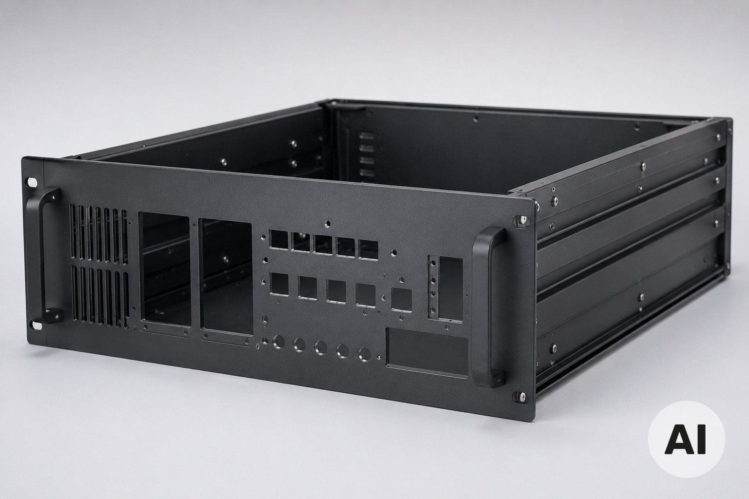
Our Capability: Custom Depth, Cutouts and Structural Reinforcement from a Standard Platform
Our engineering approach ensures a 19″ chassis never becomes a compromise. We start from standard 19″ rackmount chassis building blocks that follow IEC 60297, DIN 41494 and IEEE 1101.10, and then adapt them to your specific mechanical envelope. This means we can produce a 19 inch rack mount chassis with non-standard depth. We can also build a 19″ rack chassis with custom mounting flange positions or a 19″ enclosure with a completely different internal layout. Consequently, you gain all this without losing the benefits of standardisation.
For projects that require a compact footprint, we can supply a half-rack chassis or a shallow-depth 1U or 2U chassis. The same level of customisation applies. For larger systems, we can reinforce a 3U, 4U or 6U chassis with thicker sheet metal, additional stiffening ribs or welded corner joints. We work closely with your mechanical and PCB teams to define depth, cutout positions and mounting points before any metal is cut.
- Custom depth profiles — extend or reduce depth to match your backplane, card set or cable harness
- Precision cutouts — CNC-machined front and rear panels for connectors, displays, switches and airflow
- Structural reinforcement — thicker side plates, internal braces and reinforced mounting flanges for shock and vibration
- Surface finishing — conductive or corrosion-resistant coatings suitable for industrial, medical and outdoor use
- Fast prototyping — from 3D CAD review to a working prototype in weeks, not months
We can deliver a single 19″ enclosure for a proof-of-concept or a pre-series batch of industrial rackmount enclosures. Our in-house manufacturing capability allows quick iteration. We adjust tolerances, test fit with your PCBs and backplane, and document the final configuration for repeatable production. Ultimately, the goal is not simply to deliver a metal box. We ensure the mechanical platform supports your electrical, thermal and regulatory requirements from the first prototype onwards.