

For system integrators, panel builders, and engineering-driven procurement teams, selecting a power supply for IGBT and SiC characterization is not only about wattage.
It also involves voltage and current envelope, output ripple, remote sensing, automation interfaces, protection behavior, and whether the supply can support both static V-I sweeps and dynamic double-pulse tests without becoming the limiting factor in the measurement.
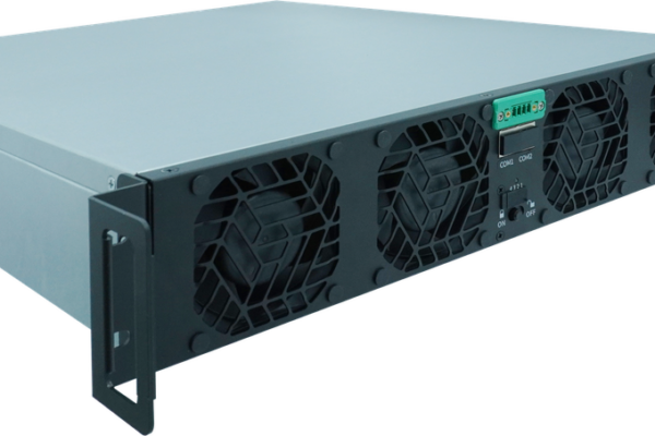
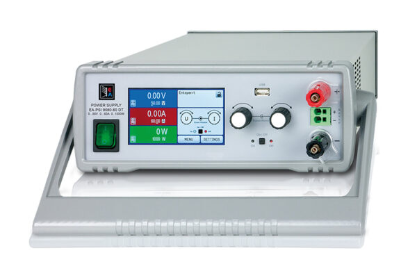
The EA-PSI 10200-210 3U is a 200V/210A/15kW programmable DC power supply in a 3U 19-inch chassis. For 12kW-class test profiles, it provides 15kW of headroom, ≤40mV rms ripple, up to 94.5% efficiency, a built-in function generator, and master-slave parallel operation up to 64 units.
Typical applications include IGBT and SiC module V-I characterization, double-pulse dynamic testing, battery and fuel-cell test systems, and automotive component validation.
1. What V-I and dynamic characterization actually require
IGBT and SiC power module characterization is usually split into two measurement domains. Static V-I curves describe the conduction behavior: collector-emitter or drain-source voltage versus current at a defined gate voltage and temperature. Dynamic characterization describes switching behavior: turn-on and turn-off transitions, reverse recovery, and the effect of gate resistance and bus inductance.
The power supply plays a different role in each domain. In static testing it is the swept source that sets the operating point. In dynamic testing it is the DC bus source that charges the capacitor bank and must remain stable while the module switches at high di/dt and dv/dt.
1.1 Static V-I curve requirements
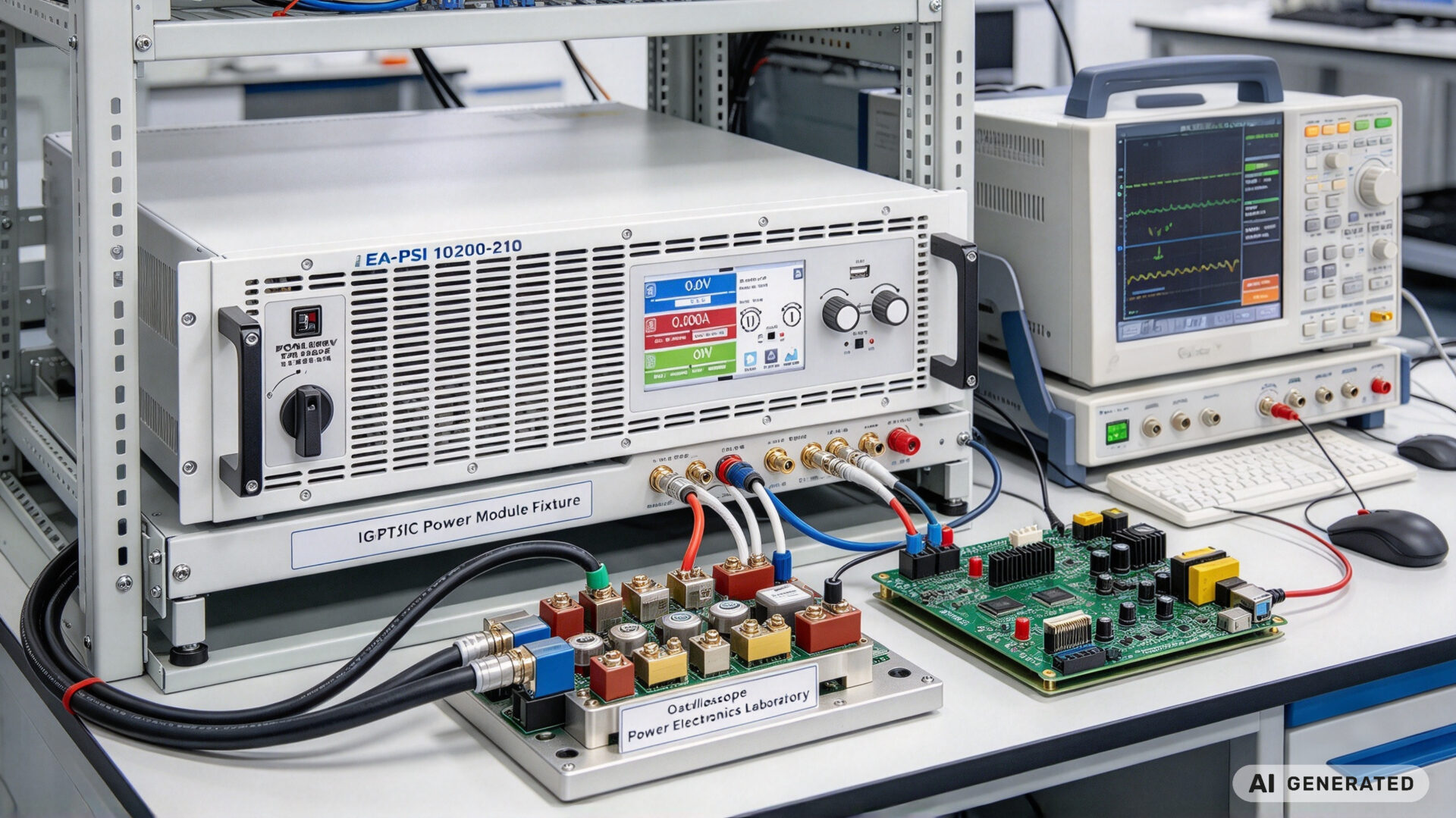
A static V-I sweep needs a supply with low output ripple, accurate voltage and current setpoints, and remote sensing at the device terminals. The measurement is usually automated: the supply steps the operating point, a shunt and differential probe measure current and voltage, and a PC logs the curve. The supply’s own noise and drift appear directly in the measured curve, so ripple and regulation are part of the measurement uncertainty budget.
The relevant device standards include IEC 60747-9 for IGBTs and the JEDEC JESD24 series for power transistors. These standards define test conditions and parameter definitions, not the power supply specification. The supply must be selected so that it does not distort those conditions.
1.2 Dynamic double-pulse requirements
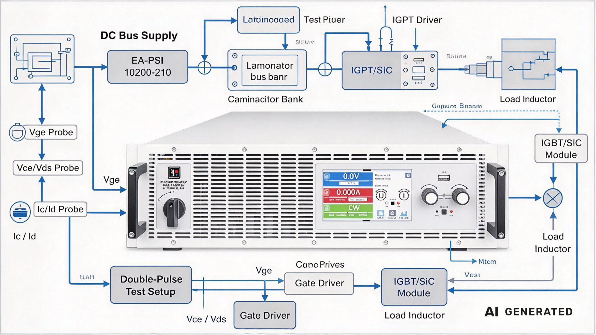
The double-pulse test uses a DC bus, a capacitor bank, a laminated busbar, a gate driver, and a load inductor. The power supply charges the capacitor bank before the pulse sequence; during the pulse, the capacitor supplies the transient current. The supply must therefore have enough voltage and current to charge the bank quickly, and enough stability that the bus voltage does not drift between pulses.
For 12kW-class test profiles, the supply must cover the bus voltage and the charging current without entering current limit during the pre-charge phase. The EA-PSI 10200-210 3U provides 200V and 210A, which covers low-voltage module testing and 200V bus dynamic tests. For full 650V or 1200V blocking-voltage characterization, a higher-voltage source or a dedicated curve tracer is required; this supply is not a substitute for a 1200V blocker test.
2. Why the EA-PSI 10200-210 3U fits 12kW-class testing
The EA-PSI 10200-210 3U delivers 200V, 210A, and 15kW in a 3U chassis. For a 12kW test profile, this leaves headroom for cable drop, capacitor pre-charge, and the difference between the setpoint and the actual operating point.
2.1 Voltage, current, and power envelope
The 200V output covers low-voltage SiC and IGBT module forward characterization, gate-loop studies, and 200V bus double-pulse tests. The 210A current covers high-current forward curves and capacitor pre-charge. The 15kW rating covers 12kW profiles without running the supply at its thermal limit, which matters when the test bench is inside a cabinet or a small lab.
2.2 Ripple, accuracy, and remote sensing
The supply specifies ≤40mV rms ripple (300kHz bandwidth) and ≤300mV pp (20MHz bandwidth). At a 200V setpoint, 40mV rms is 0.02% of the output, which is small relative to the voltage measurement resolution needed for V-I curves. Remote sensing compensates for cable and busbar voltage drop, so the setpoint is maintained at the device terminals rather than at the supply output.
For a V-I curve, the dominant error sources are usually the shunt, the probe, and the temperature control—not the supply. But a supply with high ripple or poor load regulation adds an error that cannot be calibrated out.
2.3 Function generator and automation
The integrated function generator supports sine, triangle, rectangular, trapezoidal, and arbitrary waveforms, plus DIN 40839 engine-start simulation and EN 50530 PV inverter profiles. For IGBT and SiC work, the arbitrary waveform and trapezoidal profiles are useful for bus pre-charge and for reproducing application-like voltage ramps. The supply is controlled over USB, Ethernet, or isolated analog interface, with optional CAN, Profibus, EtherCAT, ModBus TCP, RS232, and CANopen modules. SCPI and ModBus protocols allow the test sequence to be automated from a PC.
For related high-current test hardware, see the TPS-DM570T1512KIF and TPS-DM570T1512KIRF bidirectional DC-DC modules, and the broader TPS production category.
3. Test setup and workflow
A repeatable characterization workflow separates the static and dynamic setups, even when the same supply is used for both. The static setup is a precision sweep; the dynamic setup is a bus-charging and switching test.
3.1 Static V-I sweep setup
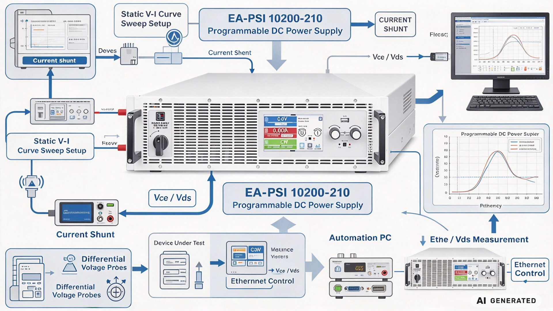
For the static sweep, connect the supply to the device through a current shunt and a decoupling network. Use remote sense at the device terminals. Set OVP and OCP to values that protect the device but do not trip during the sweep. Program a stepped or ramped sweep over SCPI, and log the shunt voltage and the differential probe voltage at each point. Keep the device temperature controlled, because V-I curves shift with temperature.
3.2 Dynamic double-pulse setup
For the double-pulse test, the supply charges the capacitor bank through a pre-charge resistor or an active pre-charge circuit. The laminated busbar minimizes stray inductance. The gate driver applies the double pulse, and the oscilloscope captures Vge, Vce/Vds, and Ic/Id. The supply must remain in voltage mode during the pulse, with the capacitor supplying the transient current. Set the current limit high enough for the pre-charge but low enough to protect the busbar and the capacitor bank.
The built-in function generator can reproduce bus voltage profiles and DIN 40839 engine-start waveforms, which is useful for application-like testing beyond the standard double pulse.
3.3 Protection and safety configuration
Configure OVP, OCP, and OPP before connecting the device. Use the user-defined events (UVD, OVD, UCD, OCD, OPD) to trigger a safe shutdown when the device behaves unexpectedly. For SiC modules, the fast switching edges can couple into the measurement and into the supply’s sense lines; keep the sense leads twisted and away from the power loop. For high-current tests, verify the busbar and connector temperature during the first runs.
4. Scaling to higher power with parallel operation
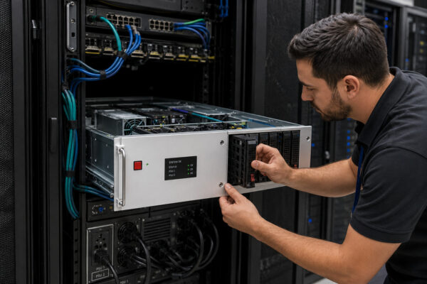
The EA-PSI 10200-210 3U supports master-slave parallel operation of up to 64 units via Share bus and digital bus, for a total system power up to 960kW with true summation of set and actual values. For module characterization, this allows a single 15kW unit to be used for 12kW profiles and expanded later for higher-power modules or for parallel testing of multiple devices.
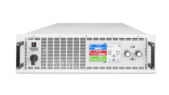
Parallel operation is also useful for high-current V-I sweeps, where the current requirement exceeds a single unit’s 210A. The current sharing must be verified at the operating point, and the protection settings must be coordinated across the master and slaves.
For more product context, see the TPS power module category and the TPS blog content.
5. RFQ checklist
To streamline quotation and evaluation for a 12kW power supply used in IGBT and SiC characterization, provide the following information:
- Device type and ratings: IGBT or SiC, blocking voltage, current rating, and gate voltage
- Static V-I requirements: Voltage and current sweep range, number of points, and measurement uncertainty target
- Dynamic test requirements: Bus voltage, pulse current, capacitor bank size, and switching frequency
- Power profile: Continuous and peak power, and whether 12kW is a continuous or intermittent requirement
- Automation interface: USB, Ethernet, CAN, EtherCAT, or ModBus TCP, and the control software environment
- Protection settings: OVP, OCP, OPP, and user-defined events required for the device under test
- Thermal environment: Rack or cabinet ambient temperature and cooling arrangement
- Documentation: Calibration certificate, test report, and interface protocol documentation
Providing these details reduces clarification cycles. TPS’s engineering team can support supply selection, parallel configuration, and test setup review as part of the RFQ process.
6. FAQ
Can the EA-PSI 10200-210 3U characterize 1200V SiC modules?
No. The output is limited to 200V. It is suitable for low-voltage forward V-I characterization, gate-loop studies, and dynamic tests with a bus voltage up to 200V. Full 650V or 1200V blocking-voltage characterization requires a higher-voltage source or a dedicated curve tracer.
Is a 12kW supply enough for double-pulse testing?
For many module-level double-pulse tests, the capacitor bank supplies the pulse current and the supply only charges the bank. A 12kW profile is usually sufficient for pre-charge and bus holding. The required supply power depends on the capacitor bank size, the bus voltage, and the allowed pre-charge time.
Why is low ripple important for V-I curves?
The supply ripple appears directly in the measured voltage and current. At low current points, ripple and noise can dominate the measurement. The EA-PSI 10200-210 3U specifies ≤40mV rms and ≤300mV pp, which is small relative to the voltage range but should still be included in the uncertainty budget.
Can the supply be automated?
Yes. It supports USB, Ethernet, and galvanically isolated analog interfaces, with optional CAN, Profibus, EtherCAT, ModBus TCP, RS232, and CANopen modules. SCPI and ModBus protocols allow integration into automated test systems.
How many units can be paralleled?
Up to 64 units via Share bus and digital bus, for a total system power up to 960kW with true summation of set and actual values.