Key Takeaways
- Successful EMS cable builds start with clear specifications for fiber optic connector types and optical fiber termination types, as these directly influence performance, cost, and lead time.
- Understanding commonly used connector families (LC, SC, FC, ST, MPO/MTP) supports compatibility with active equipment and simplifies procurement.
- Clear end-to-end documentation—explicitly listing fiber optic cable and connectors on the BOM—helps reduce rework and accelerates approval for production-ready assemblies.
- Always specify fiber mode (OS2, OM3, OM4, OM5), polish (UPC or APC), length, and end configuration for typical requests such as LC-LC or SC-to-LC jumpers.
- Buyer shorthand such as “fo cable” or “ofc connectors” should be clarified early to confirm optical fiber (not copper) and mapped to the correct connector family.
- Factory insertion-loss (IL) and return-loss (RL) testing, end-face inspection, and serial-level traceability are essential for dependable deployment.
From data centers to medical imaging environments, the quality of fiber optic cable assemblies influences signal margin, uptime, and long-term serviceability. This guide explains how EMS providers specify fiber optic cables and connectors, how connector selection impacts system compatibility, and how termination methods affect optical performance and field reliability.
What’s Inside a Fiber Optic Cable Assembly?
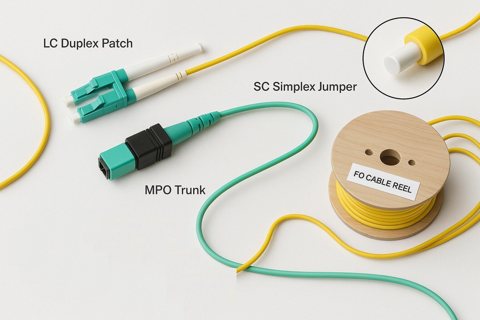
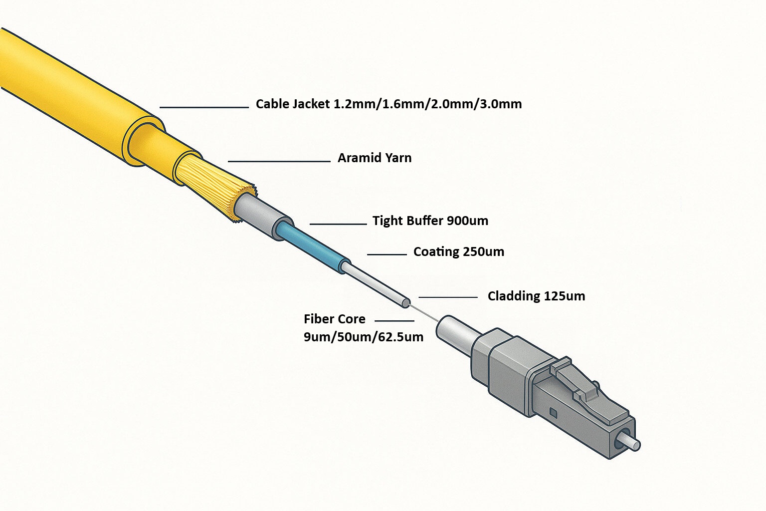
A production-ready fiber optic cable assembly combines the appropriate fiber grade—OS2 for long-reach single-mode links or OM3/OM4/OM5 for short-reach multimode applications—with compatible connector types on both ends.
Typical documentation includes polarity, jacket material, labeling scheme, and test records. Clear BOM language such as:
Fiber optic cable and connectors: LC duplex, OS2, 2.0 mm jacket, UPC polish, 10 m
helps eliminate ambiguity and supports efficient manufacturing and inspection.
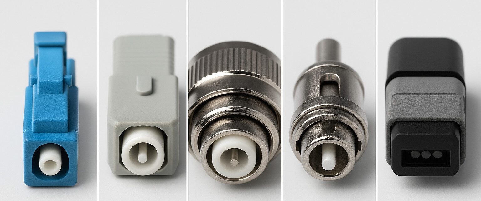
Fiber Optic Connector Types Commonly Used
- FC / ST – Threaded (FC) and bayonet-style (ST) connectors primarily used in legacy systems, laboratory setups, and industrial environments.
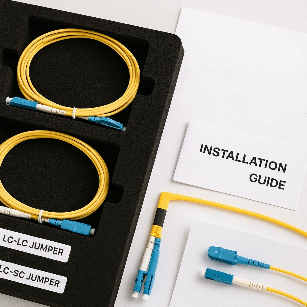
- LC – Small-form-factor connector with a 1.25 mm ferrule; widely used in high-density panels and transceiver interfaces. Common in duplex LC-LC assemblies.
- SC – 2.5 mm ferrule with push-pull latch; frequently used in enterprise and FTTH environments. Drawings specifying “SC” should also indicate polish type (UPC or APC).
- MPO/MTP – Multi-fiber connectors for parallel optics, trunk cables, and leaf-spine data-center architectures. Polarity method (A/B/C) and keying require careful definition.
Optical Fiber Termination Types
Optical fiber termination types influence both insertion loss and back-reflection characteristics.
- UPC (Ultra Physical Contact) is commonly used in duplex links where low insertion loss is required.
- APC (Angled Physical Contact) is preferred in PON, backbone, or higher-power applications where reduced back-reflection is critical.
Termination methods may include epoxy-and-polish, pre-polished splice-on connectors, or fusion-spliced pigtails. Each option presents different trade-offs in cost, production time, and field serviceability.
Specification Language That Helps Prevent Errors
To reduce misinterpretation during sourcing and manufacturing, specifications should clearly define:
- Mode & grade: OS2 (single-mode) or OM3/OM4/OM5 (multimode), including length and jacket diameter
- Connectors: Standardized connector types at both ends (e.g., LC-LC or LC-SC)
- Polish & polarity: UPC or APC; duplex polarity or MPO A/B/C mapping
- Labels & documentation: Serial numbers, IL/RL test reports, and end-face inspection images
- Terminology alignment: Informal terms such as “fo cable” or “ofc connectors” should be restated using standard optical fiber terminology in quotations and BOMs
Manufacturing & Test: How EMS Supports Reliability
EMS cable assembly involves more than connector termination. Controlled processes address cable geometry, pull strength, and minimum bend radius. End-face inspection and optical testing are performed to support consistent quality and traceability.
Typical validation steps include:
- End-face inspection and cleaning to IEC criteria
- Insertion-loss and return-loss testing per leg and polarity
- Mechanical screening for pull, flex, and temperature exposure (application-dependent)
- Labeling and optional QR-code linkage to the production record
These steps support efficient installation and help reduce commissioning time in the field.
Buyer’s Checklist
- Confirm connector types at both ends (e.g., LC-LC or LC-SC)
- Define polish (UPC/APC), fiber mode, length, jacket type, and pull-strength requirements
- Specify accessories such as dust caps, clips, labels, and routing tags
- Request IL/RL data, inspection images, and warranty terms with delivery
FAQ
Q1. Are “ofc connectors” and fiber optic connectors the same?
In most purchasing contexts, yes. “OFC connectors” is often used informally to describe optical fiber connectors. Specifications should always be restated using standard connector terminology.
Q2. What does “optical connector SC” mean on a drawing?
It identifies the SC connector family. Additional details such as UPC or APC polish and simplex or duplex configuration should be confirmed.
Q3. Can legacy “fo cable” part numbers be matched?
Yes. Historical specifications can be mapped to current fiber optic cable assemblies with documented IL/RL results.
Q4. Do you supply mixed fiber optic cable and connector kits?
Yes. Assemblies can include pre-terminated harnesses, pigtails, jumpers, and labeling packaged under a single job reference.
Q5. What is the fastest route to production?
Using standardized specification blocks—fiber mode, length, jacket, polarity, and connectors at both ends—helps most LC and SC assemblies move efficiently from quotation to testing.
TPS Elektronik manufactures and validates fiber optic cable assemblies with defined process control and documented testing—supporting confident sourcing, efficient installation, and reliable operation.


