Overview
If you place electronic products on the EU market, the European EMC Directive (2014/30/EU) requires that equipment:
- Does not generate excessive electromagnetic interference (emissions), and
- Maintains acceptable performance in the presence of electromagnetic disturbances (immunity).
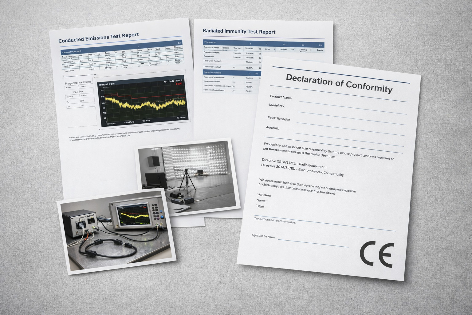
Compliance is typically demonstrated through structured EMC testing, technical documentation, and a Declaration of Conformity (DoC) supporting CE marking.
This article explains:
- The difference between EMC emissions testing and EMC immunity testing
- How to plan a reliable conducted emissions test setup
- What to consider when selecting EMC immunity test equipment and test systems
- How to move from pre-compliance to formal EMC product certification
Key Takeaways
- The European EMC Directive forms the legal basis for CE marking regarding electromagnetic compatibility.
- A structured path to EMC compliance includes planning, pre-compliance screening, formal testing, and disciplined documentation.
- Repeatable conducted emissions measurements depend on correct LISN setup, grounding, and cable layout.
- Immunity testing evaluates functional robustness under defined electromagnetic disturbances.
- Selecting an experienced, accredited laboratory can help reduce technical and scheduling risks during certification.
EMC Emissions Testing: Limiting Interference at the Source
EMC emissions testing verifies that a device’s unintended electromagnetic energy remains within applicable regulatory limits.
Two primary categories are assessed:
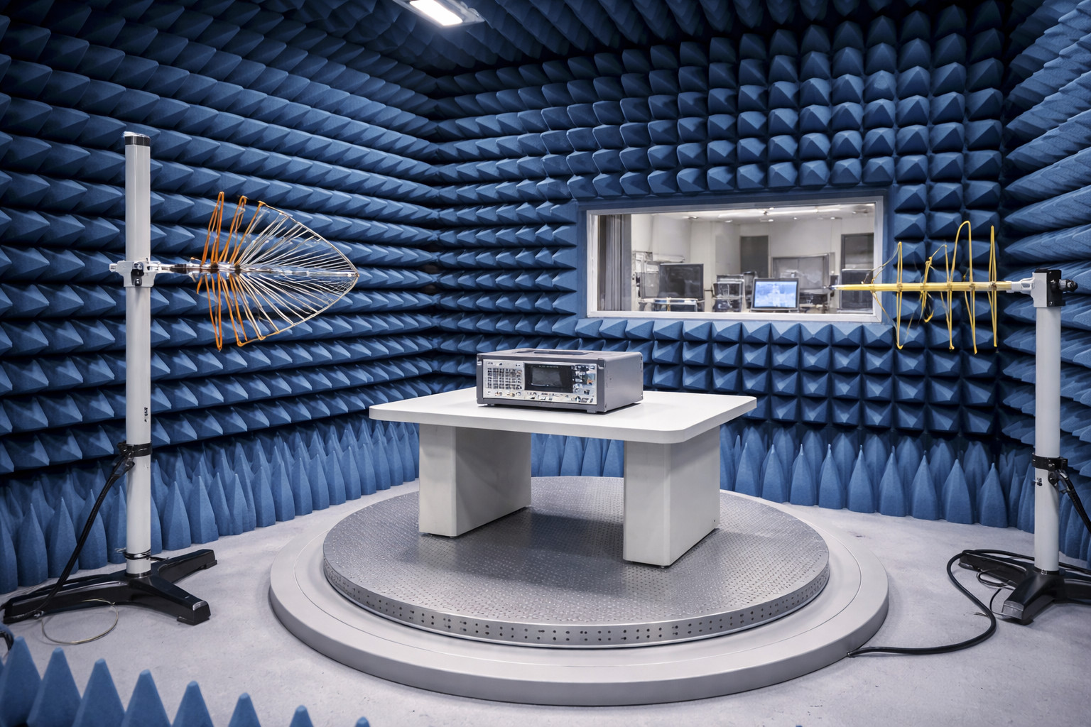
Radiated Emissions
- Measured in anechoic or semi-anechoic chambers
- Use calibrated antennas and EMI receivers
- Evaluate field strength across specified frequency ranges
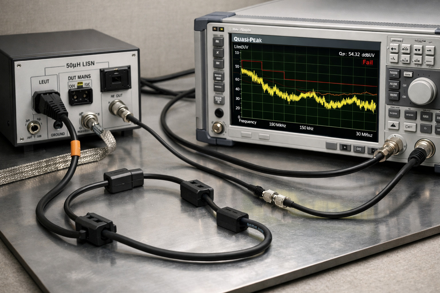
Conducted Emissions
- Measured using Line Impedance Stabilization Networks (LISNs)
- Assess noise on power and signal lines
- Typically evaluated using quasi-peak (QP) and average (AVG) detectors
Ensuring a Repeatable Conducted Emissions Test Setup
A reliable setup reduces measurement uncertainty and avoids unnecessary redesign loops. Key elements include:
- Defined cable routing and length
- Correct grounding plane configuration
- Proper LISN placement and bonding
- Documented receiver settings and bandwidth
Small variations in layout can significantly affect results. A documented and consistent setup is therefore essential for repeatability.
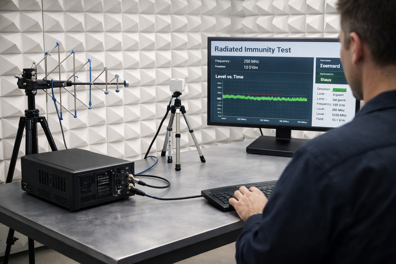
EMC Immunity Testing: Verifying Functional Robustness
While emissions focus on limiting disturbance, EMC immunity testing evaluates how a product behaves when exposed to external electromagnetic stress.
Typical immunity tests include:
- Radiated RF fields
- Conducted RF disturbances
- Electrostatic discharge (ESD)
- Electrical fast transients (EFT)
- Surge
- Voltage dips and interruptions
- Power-frequency magnetic fields
A laboratory integrates signal generators, amplifiers, antennas, coupling networks, ESD guns, and monitoring systems into a calibrated EMC immunity test system. The objective is to expose the Equipment Under Test (EUT) to defined disturbance levels and evaluate performance criteria specified in the applicable standard.
In practical terms, immunity testing demonstrates whether a product maintains acceptable operation in typical electromagnetic environments.
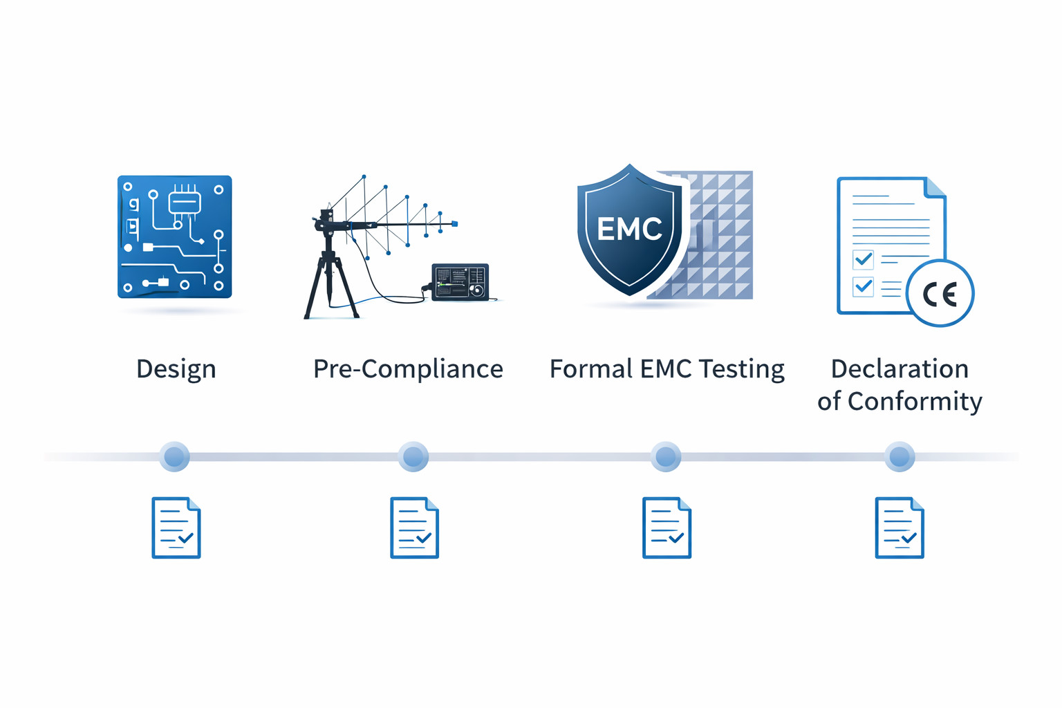
From Pre-Compliance to EMC Product Certification
A structured process helps manage technical risk and avoid late-stage surprises.
1. Planning
- Identify applicable harmonized standards (EU and, if relevant, other markets).
- Define operating modes, accessories, and worst-case configurations.
- Align firmware versions and hardware revisions before formal testing.
2. Pre-Compliance Screening
Early testing can identify emission hotspots and immunity weaknesses before booking accredited chambers.
Common tools include:
- Near-field probes
- Portable EMI receivers
- GTEM cells or absorber-lined rooms
Pre-compliance does not replace formal certification but can help reduce redesign cycles.
3. Formal Testing
In an accredited EMC laboratory:
- Emissions and immunity suites are executed according to the relevant standards.
- EUT behavior is documented under each test condition.
- Deviations, observations, and software versions are recorded.
4. Technical Documentation
Under the European EMC Directive, manufacturers must maintain a technical file including:
- Schematics and PCB layouts
- Bill of materials
- Risk analysis
- Test reports
- EU Declaration of Conformity
This documentation must be available to market surveillance authorities upon request.
Design Practices That Support EMC Compliance
Certain design measures can contribute to improved EMC performance:
- Minimize loop areas through controlled differential routing and solid return paths.
- Control edge rates and manage clock harmonics.
- Place filters and common-mode chokes close to I/O boundaries.
- Bond cable shields with low-impedance 360° connections; avoid long pigtails.
- Implement firmware strategies such as retries, timeouts, and defined brownout behavior aligned with immunity test conditions.
While no design approach guarantees compliance, integrating EMC considerations early in development typically reduces later modifications.
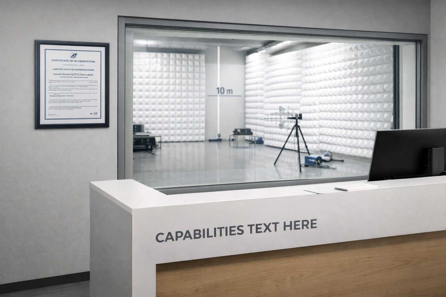
Selecting the Right EMC Laboratory
When choosing an EMC lab, consider:
- ISO/IEC 17025 accreditation
- Chamber size and frequency range compatibility
- Available emissions and immunity test equipment
- Lead times and scheduling flexibility
- Engineering support for interpretation of results
Experienced laboratory engineers can provide guidance on standard interpretation and potential corrective actions, which may support a more efficient certification process.
FAQ
Q1. What is EMC immunity testing?
EMC immunity testing exposes a product to defined electromagnetic disturbances (e.g., radiated fields, conducted RF, ESD, surge) and evaluates whether it maintains acceptable performance according to the relevant standard.
Q2. What is the difference between emissions and immunity testing?
- Emissions testing measures the electromagnetic noise generated by a device.
- Immunity testing evaluates the device’s response to external disturbances.
Both aspects are required for CE marking under the European EMC Directive.
Q3. Which immunity tests often present challenges?
Frequent technical challenges include:
- ESD at user-accessible points
- Conducted RF on long external cables
- Radiated immunity issues at enclosure seams
Early attention to shielding, bonding, and filtering can help mitigate these risks.
Q4. Is pre-compliance testing necessary?
Pre-compliance testing is not mandatory under the Directive. However, it can help identify potential issues before formal testing and may reduce redesign effort.
Q5. How is a conducted emissions setup documented?
Laboratories typically record:
- Cable length and positioning
- LISN type and configuration
- Detector settings (QP/AVG)
- Environmental conditions
This documentation ensures traceability and repeatability across retests.