Key Takeaways
- Integrating hardware circuit breaker panel design with the software circuit breaker pattern supports resilient systems across electrical and digital domains.
- Effective circuit breaker system design begins with system-level analysis: fault levels, selectivity, and environmental conditions.
- Coordinated ECAD workflows (e.g., Altium Designer and Cadence Allegro) help ensure layout consistency, manufacturability, and documentation quality.
- MCAD integration (e.g., SolidWorks mechanism and packaging design) reduces mechanical risks and late-stage changes.
- FPGA-based embedded design enables deterministic I/O, hardware acceleration, and hardware-in-the-loop (HIL) validation.
- Retrofit circuit breaker design requires careful adaptation to modern standards and updated protection requirements.
Modern development teams often deal with two types of “circuit breakers.”
- The physical protection device in electrical distribution systems.
- The software resiliency pattern used in distributed applications.
Although they operate in different domains, both serve the same objective: limiting failures and preventing cascading effects. This article outlines how to integrate hardware protection, software resiliency patterns, and ECAD/MCAD/FPGA workflows into a coordinated development process.
Part 1 — Hardware: Circuit Breaker System Design & Panel Coordination
In power distribution systems, a circuit breaker is designed to detect abnormal currents and interrupt them according to a defined time–current characteristic.
Effective circuit breaker system design begins with:
- Short-circuit analysis
- Protection coordination studies
- Environmental and installation assessments
For both new installations and retrofit circuit breaker design projects, the following aspects are evaluated before finalizing the circuit breaker panel design:
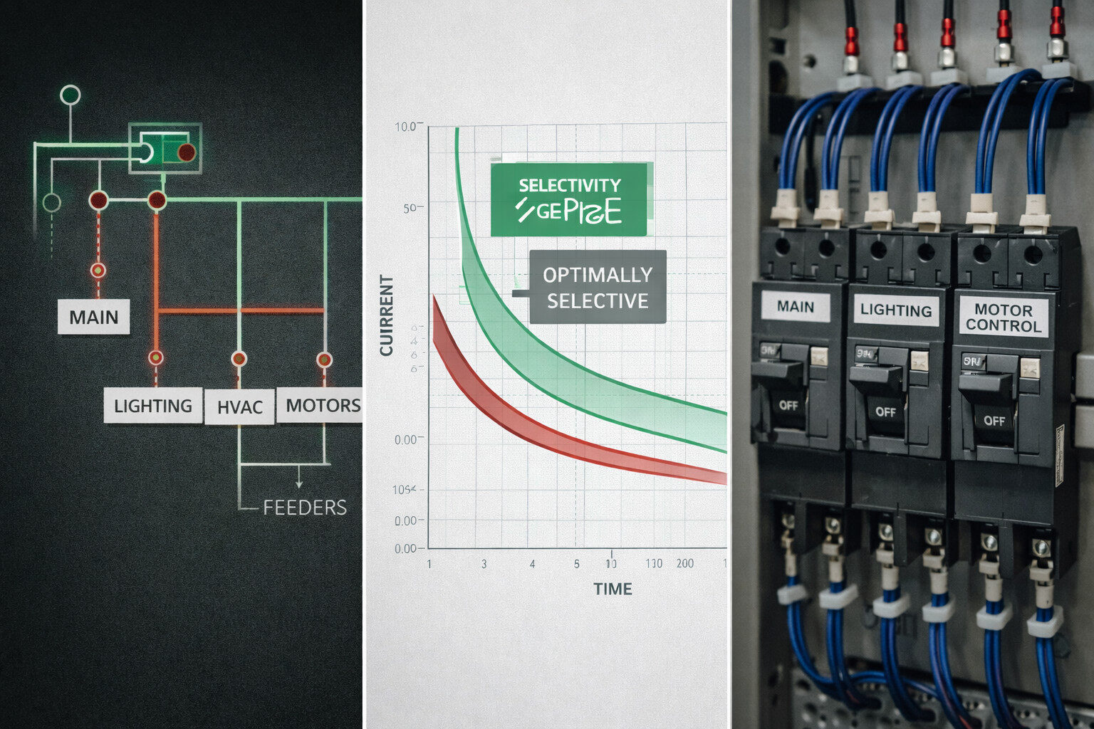
Selectivity & Coordination
- Downstream devices should trip before upstream devices.
- Time–current curves must be aligned to maintain operational continuity.
Thermal & Derating Considerations
- Ambient temperature and enclosure conditions influence trip behavior.
- Conductor sizing and heat dissipation paths affect long-term reliability.
Documentation & Compliance
- Single-line diagrams
- Protection coordination studies
- Test documentation
These records are essential for technical validation and audit processes.
Part 2 — Software: The Circuit Breaker Design Pattern in Distributed Systems
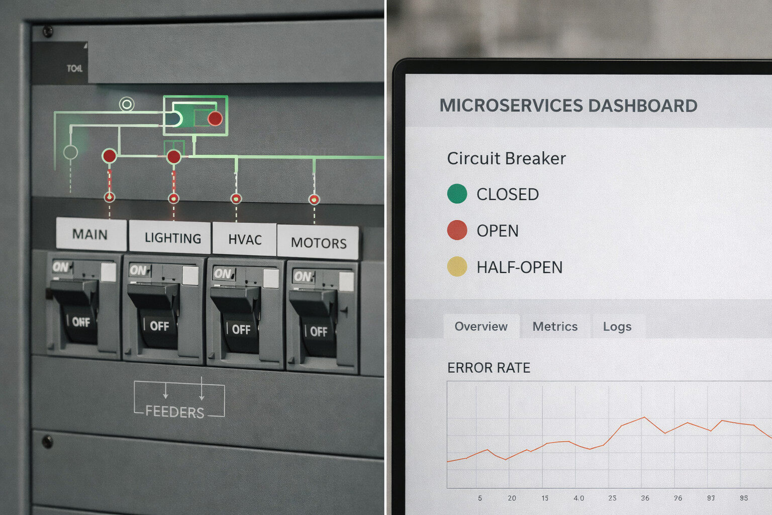
The circuit breaker design pattern protects applications from unstable dependencies.
When defined thresholds are exceeded—such as error rates or latency—the breaker transitions from Closed to Open, blocking calls and optionally activating fallback logic. After a defined interval, it moves to Half-Open to test recovery before returning to normal operation.
Typical Monitoring Signals
- Rolling error rate
- P99 latency
- Timeout frequency
- Backoff and retry metrics
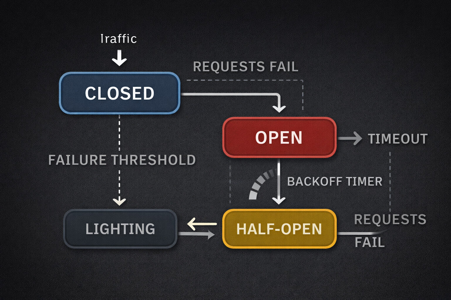
Breaker States
- Closed → Open → Half-Open
- Often combined with exponential backoff strategies
Observability Requirements
- State transition events
- Fallback invocation counters
- Alerting aligned with service-level objectives (SLOs)
A standardized configuration and telemetry approach enables consistent adoption across product teams.
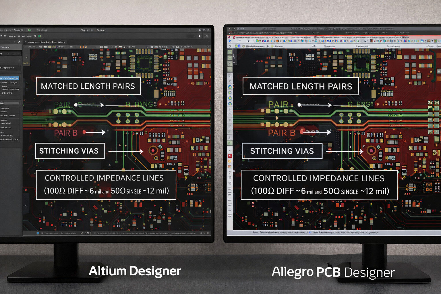
Part 3 — ECAD: Coordinated PCB Layout Workflows
Reliable hardware protection depends on robust PCB design practices.
A coordinated ECAD workflow may combine:
- Altium Designer for schematic capture and PCB layout
- Cross-validation in Cadence Allegro for rule consistency and constraint checks
Key practices include:
- Controlled impedance definition
- Return path verification
- Net class consistency across tools
- Design rule checks (DRC) per release
- Assembly-ready documentation output
Cross-tool validation can help reduce layout inconsistencies and improve manufacturability before release.
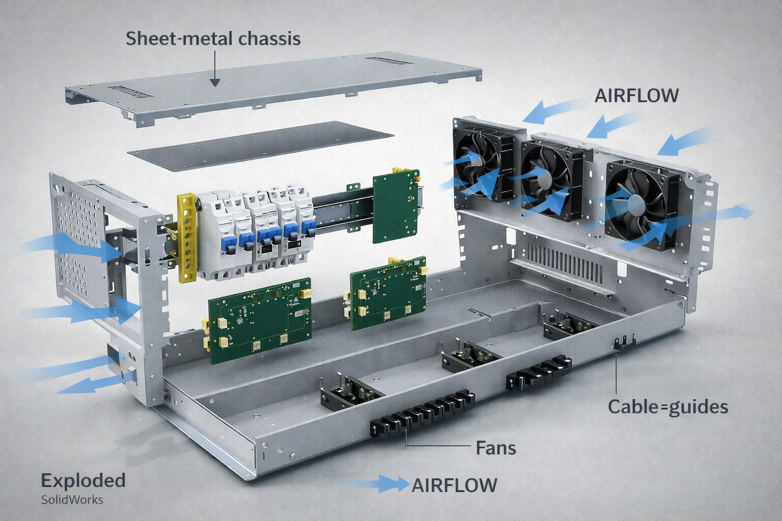
Part 4 — MCAD: Mechanical Integration & Mechanism Design
Mechanical packaging is critical for long-term reliability.
Using SolidWorks for mechanism and enclosure design allows teams to:
- Validate clearances and tolerances
- Model harness bend radii
- Assess airflow and cooling paths
- Plan service access
Early-stage prototypes may start with basic assemblies, while production designs require advanced interference checks and integration with ECAD data.
Consistent ECAD–MCAD data exchange helps prevent late-stage conflicts and reduces iteration cycles.
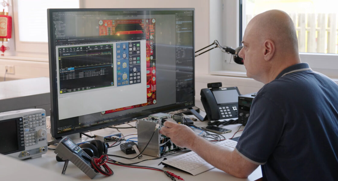
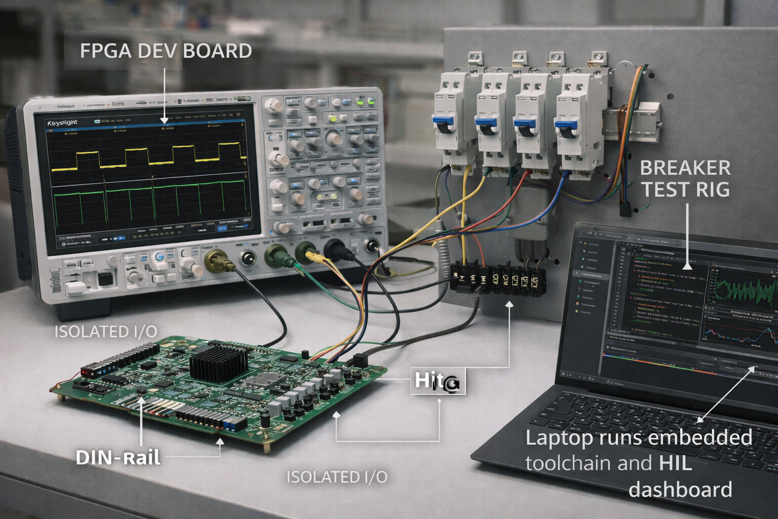
Part 5 — FPGA & Embedded System Integration
For applications requiring deterministic timing or low-latency control, FPGA-based design can complement traditional firmware.
Typical use cases include:
- Signal filtering
- Safety interlocks
- Deterministic I/O handling
Hardware-in-the-loop (HIL) test benches support timing validation while enabling concurrent updates across ECAD and MCAD domains.
A shared digital workflow improves traceability and reduces integration risks.
Quick Start Checklist
Hardware Protection
- Complete fault and selectivity studies before panel finalization.
- Validate environmental and thermal constraints.
Software Resilience
- Implement the circuit breaker pattern with defined thresholds and monitoring.
- Align alerts with SLOs.
ECAD/MCAD Synchronization
- Run DRC checks and interference analyses for each release.
- Maintain consistent constraint definitions across tools.
Prototyping & Validation
- Simulate fault scenarios.
- Use HIL testing where deterministic timing is critical.
- Document validation results systematically.
Integrated Development Approach
Combining hardware protection engineering, software resilience patterns, and coordinated ECAD/MCAD/FPGA workflows can support complex product development projects.
Such integration helps align electrical safety, mechanical robustness, and software stability within a structured engineering process.


